Beam profiling promises to ease and automate fiber-lens alignment.
Dr. Derrick Peterman, John Fleischer and Dan C. Swain
In the fiber optics industry, one constantly hears that new markets
will remain elusive unless production efficiency is improved. It is a common goal,
therefore, to develop better processes. We propose beam profiling as a scalable
improvement for the alignment of a variety of fiber optic components.
Fiber-lens alignment is required in the production
of many components, including optical switches, multiplexer/demultiplexers and filters.
The light from the end of a bare fiber is highly divergent, and substantial power
is lost in the fiber optic component unless a lens is used to collimate the beam.
A fiber-lens pair is needed whenever the light from the fiber must pass through
an optical element, such as a grating, a filter or a mirror.
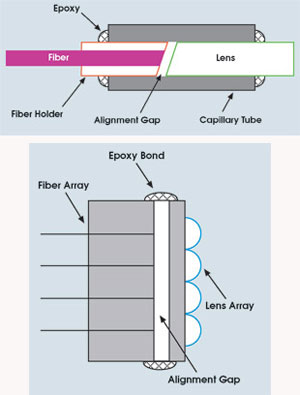
A fiber-lens pair is required whenever the light from a fiber passes through an optical
element. Lenses may be contact-bonded to the fiber (above) or precision-aligned
in proximity to it (left). Images courtesy of Photon Inc.
After the light has interacted with
the elements, it is put back into a fiber via a lens coupled to the destination
fiber. The lens can be contact-bonded to the fiber or precision-aligned in proximity
to it. Rotational and linear alignment of the fiber are critical prior to bonding.
Backreflection’s problems
The goal in alignment is to minimize insertion
loss as the light passes through the fiber-lens pair; the backreflection technique
is often employed. A mirror reflects the light from the lens into the fiber, which
couples a power meter to measure the backreflected light. The coupling is adjusted,
often manually, until the backreflected power is at maximum. To a degree, the insertion
loss can be determined by reading the power meter.
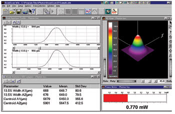
Beam profiling quantifies orthogonal profiles, power, and beam
width
and position, and offers a three-dimensional representation of the beam.
The technique is common throughout
the industry, but it suffers from several problems. For example, because the operator
usually manually adjusts the mirror, the process is open to variation and is dependent
upon operator skill.
Ideally, the process would be automated,
but it is difficult to determine a robust algorithm for optimal coupling. Moreover,
it is difficult to quantify the process other than simply minimizing loss. Parameters
that may be critical to coupling, such as the pointing of the beam, are only inferred.
In fact, one can determine if a fiber-lens pair is “lossy,” but not
the source of that loss.
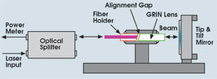
The backreflection technique is commonly used to minimize insertion
loss. A tip-and-tilt
mirror reflects the light through the fiber-lens pair. The technique
suffers from several
problems.
Again, at best, only one parameter
is quantified, and low insertion loss does not necessarily indicate good optical
performance because there are a host of optical alignment issues to consider.
Quantifying coupling
In contrast, profiling the light as it is emitted
through the fiber-lens pair provides a quantifiable, repeatable means to improve
and automate this process. Profiling the light yields more information than the
backreflection technique. The cause of poor alignment can be identified and tracked
from the beam-profile data, enabling the appropriate corrective actions to be taken
before value is added to that assembly or process.
Parameters that quantify fiber-lens
coupling are beam width; beam position or pointing; beam collimation or waist along
the optical axis; general features of beam profile, including Gaussian fit; and
beam power:
• Beam width. The beam
width is a function of the distance between the fiber and the collimating lens when
measured at positions along the optical axis of the beam. In some cases, beam width
at a given distance from the lens quantifies coupling and correlates to the insertion
loss of the lens coupling.
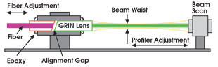
Profiling the light from the fiber-lens pair offers more
information
than the backreflection technique, enabling the development of automated
alignment
processes.
• Beam position/pointing.
If the light emerges at an angle to the optical axis, much of its power will be
lost in the device. A component that displays low insertion loss but features incorrect
beam pointing often fails to deliver optimum system performance. Beam pointing is
especially important for microelectromechanical optical switching applications,
in which the alignment of the light on the reflecting mirror is critical.
• Collimation/beam waist.
Measuring the beam width at points along the optical path indicates collimation.
For a collimating lens, it directly measures the performance of the lens and its
alignment with the fiber. In addition, coupling the light between two fiber-lens
pairs is at a maximum when the positions of the waists overlap. Collimation measurement
can be automated by mounting the beam profiler onto a motorized stage, enabling
accurate and quick positioning while collecting the data.
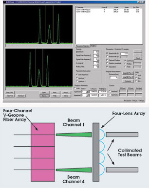
As fiber arrays become more common, it is increasingly important
to be able to analyze multiple
beams simultaneously. Here, beam profiling analyzes three beams (top).
For complex
arrays (bottom), the profiler can be repositioned to collect data from
various parts
of the array and at different working distances.
• General features. A
profile that deviates significantly from a Gaussian may indicate a defect in the
lens or poor alignment between the elements. A non-Gaussian profile may indicate
the presence of higher-order modes in the beam. Because different modes propagate
at different speeds, mode dispersion will increase the bit error rate introduced
by the optical component.
• Power. Some profiling
instruments also measure beam power, enabling the simultaneous quantification of
transmitted power and beam profile.
The profiling process
Based on our experience with beam-profiling instrumentation
and on the requirements of the fiber-lens alignment process, we recommend the scanning-slit
technique for this application.1,2 It offers submicron accuracy and resolution of
the beam position and width. Slits can be manufactured as small as 1 μm, and
data sampling can occur at the submicron level. The single detector helps to ensure
a uniform response across the detection plane. Slit-based profilers also measure
beam power with high accuracy and resolution.
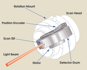
The scanning-slit technique is
suited to alignment by beam profiling. Light emerging from the fiber-lens pair passes
through the slit onto a photodetector. The photocurrent as a function of the position
of the slit generates the profile.
But whatever type of profiler is selected,
it is critical that the instrument have a means of communicating with the other
components in the manufacturing process, such as through ActiveX, GPIB command sets
or a software-development kit for automation.
The process looks like this:
• From an initial position, the
fiber or array is illuminated. The beam profile, along with other relevant parameters,
is acquired.
• Parameters measured from the
profile are loaded into an alignment algorithm that controls the fiber or array
position. The algorithm is based on previous empirical results and can include positioning
formulas, look-up tables, offset calculations or various combinations of data processing
and measurements.
• In this closed-loop process,
the fiber or array is actively positioned until the fiber-lens alignment meets the
predetermined acceptance criteria.
• Once the beam profile meets
quality-assurance limits, epoxy is applied to fix the alignment. During the curing
process, profile data is sent back to the positioning system to maintain accuracy.
The components are cured completely before the assembly is removed from the alignment
tool for the next production step.
This technique offers scalability,
repeatability and feedback on the production process. It can display varying levels
of automation, depending on the required throughput and the maturity of the process.
The alignment can be performed manually, or it can be automated using positioning
mechanisms. As the process becomes better understood, or as factors dictate improvement,
additional automation can be introduced.
This method produces repeatable components
because more than power loss data is used. Fiber-lens pairs or arrays may display
low loss, but they also can produce different beam widths or beam pointing and,
therefore, may act differently in a larger optical assembly. Several parameters
can be used to quantify alignment with beam profilers so that the fiber-lens pairs
or arrays can be optimized and manufactured in a much more controllable manner day
by day.
Finally, if a fiber-lens pair or an
array fails, analyzing the data that are collected with that part identifies the
cause quickly. Contrast this with the backreflection method, which fails a part
without offering further information to guide the process engineer. In addition,
because alignment is monitored over time, if the process is in danger of yielding
numerous product failures, the engineer can intervene before a catastrophic number
of failures occur. Conversely, the parts that show unusually high quality can be
analyzed for clues to optimize the process.
As the fiber optic industry evolves,
production efficiency must improve. There is an ongoing industrywide debate as to
the best approach to automated production. Some preach standardization; others closely
guard their proprietary methods.
The path for manufacturing
Many in the investment community predict that
production efficiencies in fiber optics will follow the transformation in semiconductors
to high-volume manufacturing, but the jury is still out regarding whether an industry
built on electrons has something to offer one built on photons. Whatever the outcome,
we expect beam-profiling instrumentation to play a significant role.
References
1. T.F. Johnston and J.M. Fleischer (April 1995).
Measurement of the absolute accuracy (to <0.5%) of a clip-level beam profiler
using Fresnel diffraction by a wide slit. Proc. SPIE, pp. 234-240.
2. T.F. Johnston Jr. and J.M. Fleischer
(April 1996). Calibration standard for laser beam profilers: method for absolute
accuracy measurement with a Fresnel diffraction test pattern. Applied Optics,
pp. 1719-1734.
Meet the authors
Derrick Peterman, John Fleischer and Dan C. Swain
are a sales engineer, the president and an automation engineer, respectively, at
Photon Inc. in San Jose, Calif.