As laser diodes continue their drive to the head of the class, instrumentation that provides test and measurement support is not far behind.
Larry Johnson and Jim Schreiner
Semiconductor laser diodes have taken the laser market by storm, in part because of their operating efficiency and compactness. They have several unique characteristics, though, that
must be considered in their application (Figure 1). These include their physical
packaging, low voltage, current-sensitive power supply requirements, temperature
sensitivity, optical output power, spectral characteristics and beam divergence.
Not surprisingly, as demand for the lasers grows, so does the need for instruments
to support their test and measurement requirements.
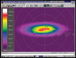
Figure 1. The far-field pattern of a laser diode depicts light intensity as a function of angle. The highly asymmetric pattern of a typical edge-emitting laser is apparent. Courtesy of Photon Inc.
Fundamentally, all laser diodes are semiconductor
PN-junction devices with a gain region, an optical waveguide and a resonant cavity.
A common edge-emitting structure has a planar optical waveguide consisting of multiple
crystalline layers of controlled consistency and doping grown on a suitable substrate
material (Figure 2). A Fabry-Perot laser structure has a resonant cavity formed
by careful cleaving of the bulk material to create parallel end facets that act
as mirrors. Optical gain results from passing electrical current through the PN
junction. At high current densities, a large population of excited electrons become
available to provide gain in the form of stimulated emission.
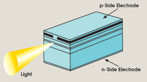
Figure 2. Typical edge-emitting laser diodes feature a planar optical waveguide fabricated in material combinations such as InGaAsP and InP.
Electrically, edge-emitting laser diodes
behave like other semiconductor diodes with a forward voltage of about 1.7 at room
temperature. As the current increases in the laser junction, gain also grows until
round-trip gain in the cavity exceeds round-trip loss, and lasing action begins.
Manufacturers describe the most basic electrical and optical properties of these
devices in a light-current-voltage plot (Figure 3). Many of these curves also include
the output current of a monitor photodiode, which comes with most laser diode packages.
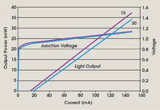
Figure 3. Light-current-voltage characteristics curves provide information on basic operating parameters of diodes.
The optical spectrum of light emitted
by laser diodes varies in center wavelength and in spectral distribution, depending
on the type of device and its operating parameters. The output beam depends on the
dimensions of the optical waveguide cavity. A typical 10-mW, 780-nm laser diode
might have an effective cavity cross section of 2 x 10 μm, which gives rise
to a highly divergent and asymmetrical beam pattern.
Demand for these lasers has fueled
a new class of test instrumentation for both laboratory and production environments.
Special fixtures securely hold laser diodes and provide necessary heat sinking.
Current sources produce precision, low-noise transient-free power under all operating
conditions. Temperature controllers work with Peltier coolers and thermistor temperature
sensors to achieve a known, stable operating temperature. Optical power measurement
sensors accurately measure the highly divergent free-space beam. When the diverging
beam pattern must be characterized, far-field scanners can map the emitted light
intensity as a function of angle.
Successful equipment specification
requires careful consideration of a variety of characteristics unique to each support
tool. Mounting fixtures, for example, are critical but undervalued elements needed
for controlling a semiconductor laser.
Mounting maneuvers
Commercial mounts provide convenient electrical
connections, dependable thermal contact for temperature control, robust mechanical
mounting and suitable coupling of the output light, whether fiber-coupled or free-space.
Mounting fixtures are available for nearly all styles of laser diodes, including
window-can, dual in-line and butterfly packages.
With nonfiber-coupled packages, end
users must carefully evaluate the mount’s mechanical stability, as well as
ease of alignment with subsequent optical elements of the system. For diodes requiring
high temperature stability, such as wavelength-division-multiplexing fiber-coupled
devices, the mounting fixtures should support not only external or case temperature
control and monitoring, but also control and monitoring of an internal Peltier cooler.
For high-power laser diodes, the mounting fixture may include multiple stages of
Peltier coolers, accommodations for water cooling, and mounting holes for mating
to a larger thermal mass for improved stability and cooling capacity.
Many mounts also include an embedded
temperature-sensing element, most commonly an NTC thermistor, for monitoring the
heat sink temperature near the laser. The location of this sensor relative to the
laser diode is important when considering the overall thermal performance of the
temperature-control loop; too much distance between the diode and the sensor will
introduce thermal delays, affecting the speed and stability of the control.
Current and temperature
A variety of laser diode current sources are available,
offering a range of output currents, operating modes and protection features tailored
for semiconductor lasers. Controllers provide the convenience of current source
and temperature control in a single instrument.
Semiconductor lasers are inherently
current devices, and laser diode current sources deliver a stable, low-noise constant
output with the protective features demanded by these electrically sensitive devices
(Figure 4). Unstable or noisy injection current translates to unstable optical output
power and shifts in output wavelength. Output noise and stability specifications
should be carefully reviewed when selecting a laser diode driver.
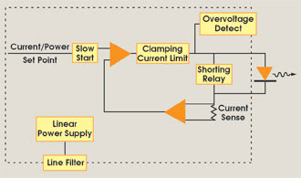
Figure 4. Instrument-grade current sources provide multiple laser protection features.
Early users of semiconductor lasers
would drive the device with a battery or other available voltage source, but these
approaches offered none of the protective features of current laser diode instrumentation.
Voltage sources may provide a smooth turn-on ramp-in voltage but, without current
control, laser output can drift with temperature.
A laser diode current source offers
selectable output current limits that clamp the output before damage can occur.
This also provides a slow-start circuit to limit start-up transients, as well as
adjustable overvoltage protection for changes in output impedance or intermittent
electrical contacts. With the output off, it is important to short connection leads
to the laser to prevent damaging surge current or discharge. Shorting field-effect
transistors or adding relays on the output stage will provide this protection in
most drivers. Finally, well-designed drivers protect against power line transients
and ensure highly controlled turn-on and shutdown modes of operation.
Another device that requires careful
control is the cooling module, because the performance of semiconductor laser diodes
is highly dependent on a stable operating temperature. Thermoelectric cooling devices
or Peltier elements are the most common ways of stabilizing temperatures of optoelectronic
devices, whether the diode is externally mounted to a thermoelectrically cooled
module or the cooling module is inside the diode package. Thermoelectric temperature
controllers provide this level of control and have additional features tailored
to the operational needs of semiconductor lasers.
he controller’s output current
should match the maximum current capacity of the cooling element, which should be
selected based on the heat load. Modern temperature controllers deliver precision
current using closed-loop control algorithms that achieve the desired temperature
set point quickly, with little oscillation. One can adjust these proportional-integral-derivative control algorithms for optimal performance for varying load characteristics. Also, a stable, low-noise current to the thermoelectric cooler minimizes the impact of coupled noise and transients.
Many controllers support a wide variety
of temperature sensors, including NTC thermistors and linear integrated circuit
temperature sensors. NTC thermistors are more common because of their low cost,
high accuracy and small size. Each sensor requires different control and sensing
signals from the instrument and may require calibration constants for accurate readings.
For instance, because the thermistor is a nonlinear device, the instrument must
support constants for a nonlinear conversion. Many thermistor suppliers provide
these constants with their devices, but the values are derivable using appropriate
measurements of resistance vs. temperature and established curve-fit programs. Linear
integrated circuit sensors depend on much simpler calibration constants.
Beam characteristics
Two other components of interest for semiconductor
laser users are optical power monitoring and far-field scanning. Selecting the best
power meter depends on such factors as dynamic power range, operating wavelength
range and output beam profile. Common power meters will satisfy a mixture of these
factors, dependent upon which are most critical to the application, and the power
and wavelength of interest (Figure 5).
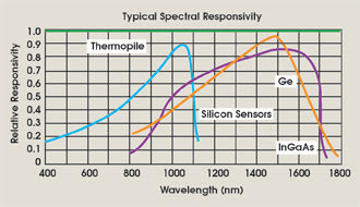
Figure 5. The spectral sensitivity of optical power measurement heads
depends on the detector used.
Launch conditions of the laser also
influence meter selection. When working with free-space or uncollimated edge-emitting
laser diodes, end users will find the output beam divergent. Thus, to get reliable
readings, the measurement head must be close enough to the device’s output
to capture all the output power. The sensor head should also be insensitive to beam
divergence.
Telecommunications lasers in dual in-line
or butterfly packages incorporate fiber pigtails, either with bare fiber terminations
or with a standard connector. Fiber optic power meters have features that optimize
power readings by reducing variability in the polarization dependencies, in the
cleave angle and angle of insertion, and in the distance between the fiber end face
and the detector. Those with an integrating sphere as the input port for the fiber
usually minimize these variants and optimize the accuracy and repeatability of fiber-based
optical power measurements.
In a manufacturing environment, the
measurement speed, accuracy and repeatability of these meters are important. They
should have fast electronics and quick processing capability. Production requirements
may also demand dual-channel capability to enable comparison with a reference signal
or with support ratio measurements.
Beam divergence can be a critical parameter
because the output beam of edge-emitting laser diodes is elliptical and highly divergent.
This occurs because the laser’s emission aperture is a narrow slit with a
long and short axis, causing diffraction effects to be stronger in one direction
than the other. The beam divergence characteristics are important in applications
where the laser output couples into a fiber or other small aperture. It is often
necessary to perform a far-field scan to measure and evaluate the spatial properties
of the diode’s output power.
Far-field scanning techniques exist
for both free-space diodes and fiber output, with the conventional method involving
the sweeping of a small-area detector through arcs in both output axes while measuring
the optical power throughout the sweep. This information creates a map of the emitted
light intensity vs. angle, essentially representing the cone of light from the diode
at the chosen far-field reference hemisphere.
For free-space diodes, this is useful
when coupling a fiber to the laser output or if collimating optics are required.
Far-field information for single- or multimode fibers is useful in calculating mode-field
diameter, effective area of the fiber and the numerical aperture, all in accordance
with TIA/EIA standards.
Laser diodes typically come in 2- to
3-in. wafers produced via metallorganic chemical vapor deposition or molecular-beam-epitaxy
processes. A good wafer can produce thousands of lasers. Between the wafer and the
final product, the devices face many test and packaging steps. Unlike silicon-based
devices, a high percentage of the final cost of a laser diode comes from these back-end
steps, where process yields are frequently low and devices may require expensive
packaging, including optical alignment.
Test systems used in laser diode manufacturing fall into three main categories:
• Parametric and functional
test systems measure operating characteristics of diodes and modules at various
processing steps. They incorporate one or more measurements, including facet light
output, monitor photodiode current and laser voltage as a function of laser diode
forward bias current; spectral properties; and far- or near-field pattern.
Later in the packaging process, engineers
will take measurements at multiple temperatures. For lasers incorporated into modules
that include thermoelectric coolers, tests to verify the operation of other module
elements include the coolers’ efficiency, and AC and thermistor resistance.
To reduce test time and cost, all parametric
and functional systems incorporate test sequence automation. Many systems feature
ganged or multiple test heads as well as some device-handling automation.
• Burn-in systems accelerate
aging of lasers during production to weed out devices that suffer from infant mortality.
A typical burn-in profile would be to operate a device in constant current mode
at 1.2 times the normal operating current and 85 °C for 200 hours, with the
laser-current-voltage characteristics measured before and after. Devices whose output
drops by more than a few percentage points would be discarded.
• Life-test systems accelerate
the aging of lasers to verify their useful life. These are similar to burn-in systems
except that they involve more complex monitoring during test, and test times run
from 3000 to 5000 hours. Although many burn-in systems simply supply a constant
current to the laser during the test, life-test systems almost always monitor facet
output, laser voltage and photodiode output (if present).
Instrumentation and test systems have
come a long way over the past 20 years to support the applications of laser diodes.
Understanding their characteristics and selecting the right equipment should increase
productivity and help achieve desired results in manufacturing or in research.
Meet the authors
Larry Johnson is president and CEO of ILX Lightwave Corp. in Bozeman, Mont.
Jim Schreiner is vice president of instrumentation products at ILX Lightwave.