Advanced manufacturing technology brings the benefits of aspheric surfaces to more applications.
Tom Miller, Newport Corp.
The use of aspheric surfaces offers the optical designer a way to achieve high performance with a minimum number of lens elements. However, the difficulty and expense traditionally associated with manufacturing high-quality aspheric optics has limited their use to specialized areas. Over the past few years, a fabrication technology called magnetorheological finishing has been developed that provides advantages over traditional production methods.
The good and bad of aspheres
One advantage of this technology is that it offers a way to produce high-precision aspheres in moderate volume. A planoconvex lens with a spherical surface focuses incoming rays, all of which are parallel to the optical axis (collimated light) (Figure 1). In the figure, there is no place along the optical axis where all the rays converge to a perfect point focus. The spherical shape of the lens surface causes this focus error, which is termed spherical aberration. In contrast, a planoconvex lens can be designed with an aspheric surface that theoretically focuses all incoming light rays parallel to the optical axis to a single point.
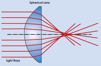
Figure 1. Spherical aberration prevents incoming collimated light rays from reaching a common point focus, limiting optical system performance.
In most lens systems, designers must use multiple surfaces to overcome spherical aberration. Added elements translate into more complex alignment and mounting, greater weight and, sometimes, higher cost. Aspheric lenses can provide the optical designer with a powerful option that often attains performance, packaging or cost goals that might be difficult or impossible using spherical surfaces alone.
Why, then, are aspheres not used more extensively in optical designs? The problem lies with the traditional methods used for optics fabrication (Figure 2). To produce spherical parts, the lens blanks are polished between convex and concave parts of the intended radius of curvature using an abrasive slurry.
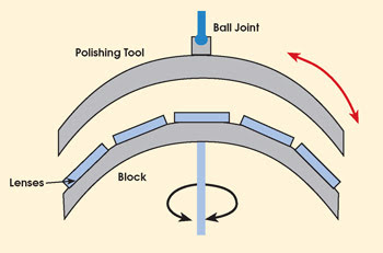
Figure 2. In traditional polishing, a grinding tool wears against components held on a block. This naturally leads to the production of spherical surfaces.
The semirandom movement of a convex spherical surface against a concave spherical surface tends to produce a spherical wear pattern. So even if the lens blanks don’t start out with a perfect spherical shape, over time, wear from the polishing process causes them to take on this shape. Moreover, with appropriate process control, this method can be controlled to an extremely high degree of precision. For example, lenses with λ/4 or better surface accuracy at 632.8 nm — a surface that is spherical to within 0.158 μm, or just six-millionths of an inch — are readily available.
However, to produce aspheric surfaces, the movement of the polishing tool must be constrained. For lenses in which the aspheric profile departs from a sphere only a small amount, it is typical to start by polishing the closest-fit sphere using standard techniques. The final aspheric shape is then achieved with a polishing tool that is much smaller than the optic (a subaperture tool) on a modified polishing machine. By controlling the amount of time that the tool spends working a particular zone of the lens, a specific aspheric profile can be produced.
If the aspheric shape departs significantly from spherical, a computer numerical control generator would typically be used to generate the aspheric shape directly into the lens blank. Alternatively, a special grinding tool can be used to transform the closest-fit sphere into a close approximation of the final desired shape. Once the blank closely resembles the desired asphere, the goal is to polish it without removing a significant amount of material. This is again accomplished using a modified form of traditional polishing apparatus and a subaperture polishing lap.
Unfortunately, because there are many environmental and operator-dependent variables in this type of polishing, successfully running this process requires a high degree of operator skill. Given the mechanical limitations of the machinery commonly employed, it is hard to achieve surface precision of λ/20 or above. Process times are measured in hours — even days or weeks, in some cases. The result is that high-quality aspheres produced in this way can be prohibitively expensive compared with spherical lenses.
Overcoming limitations
Magnetorheological finishing technology, which was developed by the Center for Optics Manufacturing at the University of Rochester in New York and commercialized by QED Technologies Inc., also in Rochester, was put in place to overcome the limitations of traditional optical polishing techniques. It is a controlled, deterministic way of producing high-precision aspheres that can be used reliably and in volume. It also potentially requires less operator know-how than traditional approaches, reduces process times significantly and can yield surface precision to λ/40.
The essential elements of the system include a pump that continuously supplies a small amount of magnetorheological fluid from a reservoir. This fluid is extruded onto a rotating wheel that draws it out into a thin ribbon. The optic to be polished is partially immersed in this moving ribbon of fluid. A specially designed electromagnet beneath the polishing wheel produces a strong local magnetic field gradient. When the moving fluid enters this magnetic field, it stiffens substantially in a matter of milliseconds; it returns to its fluid state as it leaves the field. This zone of stiffened fluid is the polishing tool. After the fluid passes the optic, it is removed by suction and pumped back into the reservoir (Figure 3).
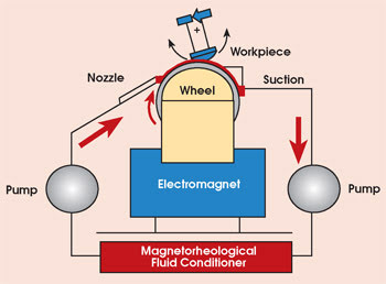
Figure 3. A magnetorheological finishing apparatus comprises the above essential elements.
A polishing session begins by running a test routine that characterizes the exact shape and removal properties of the fluid polishing tool at that time. To polish a given lens, the initial surface error (the difference between the present and desired shape) of the optic is supplied to the system software. The software uses this information to generate a set of instructions to the computer numerical control machine that moves the lens.
During polishing, the machine rotates the lens on its spindle (Figure 4). At the same time, it slowly tilts the part so that different zones in the optic are exposed to the fluid. During this process, the machine maintains a constant gap and surface normal for the part in the fluid. The computer program controls the speeds of these movements to produce the necessary amount of material removal. In other words, the system will spend more time polishing a zone with a high spot than it will spend polishing a low spot.
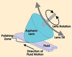
Figure 4. A closer look at the lens at the polishing zone (right) shows how the optic is slightly immersed in a thin ribbon of fluid.
This process is deterministic because the characteristics of the polishing tool are known and do not change with time. This makes dwell time in the polishing area the only variable that needs to be controlled to achieve a specific amount of material removal from a particular lens zone. This is the heart of the magnetorheological finishing technique.
The state of the polishing tool remains invariant because of its fluid nature. The fluid polishing lap conforms perfectly to the shape of the component at all times. This stands in contrast to traditional optical polishing, where wear can make the tool’s contact with the workpiece intermittent and unpredictable. The machine continuously monitors and controls the properties of the fluid, such as temperature, viscosity and evaporation rate, to maintain process invariance.
The nature of the force exerted by the finishing machine is also different from traditional polishing. In the area where the component contacts the polishing fluid, it squeezes the ribbon of fluid from its original thickness of about 2 mm down to about 1 mm. As the optic rotates against this stiffened and squeezed zone of fluid, shear stresses produce the polishing action. Traditional polishing exerts a normal force against the workpiece.
This combination of shear stress and perfect tool contact translates into high removal rates for the finishing process. In fact, aspheric surfaces with precision levels of λ/20 can be produced in a matter of minutes. The magnetorheological finishing process has also been shown to yield parts with less subsurface damage than traditional polishing methods.
An aspheric beam shaper
Newport Corp. of Irvine, Calif., uses aspheric lenses for one of its own products, a refractive beam shaper. This optical system converts an input Gaussian beam profile, common to many lasers, into a uniform intensity distribution. This product has applications in data storage, materials processing, biomedicine and electro-optics. The design, originated by John Hoffnagle and Michael Jefferson of IBM Research in San Jose, Calif., is manufactured by Newport using magnetorheological polishing.
There have been many attempts to design an efficient (low light loss) optical system to transform a Gaussian intensity distribution into a uniform intensity distribution. However, this design also offers the combination of performance, manufacturability and ease of use.
The system consists of just two plano-aspheric lenses (Figure 5). The first lens is shaped so as to produce higher magnification for rays impinging near the optical axis than for rays incident near the edge of the lens. This produces the desired change in intensity distribution at the surface of the second lens, which then recollimates the beam.
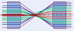
Figure 5. The magnification of the input lens of the beam shaper varies with aperture, so that the higher intensity at the center of the Gaussian beam (represented by the closer rays) is spread more than the lower-intensity light near the edge. The second lens simply recollimates the light.
Both aspheres are fabricated from fused silica. The low dispersion (change in refractive index with wavelength) of fused silica, together with the small incidence angles used in the design, makes ray paths relatively independent of wavelength. This means that the device performs the intensity transformation properly over a very wide wavelength range. All that is required is adjustment of the spacing between elements to accommodate a change in input wavelength.
The same functionality of this beam shaper could be achieved with all spherical surfaces; however, it would take several elements. The disadvantage of this is that alignment and tolerance effects in a multielement system become problematic. The system could also utilize a Galilean design; namely, with a negative aspheric first lens. However, the shape of the negative lens required is significantly more complex and difficult to manufacture than the aspheres used in the all-positive design, which are all monotonic, convex curves.
For optimum performance, the beam shaper needs an input Gaussian beam with a diameter (at the 1/e2 points) of 4.7 mm. The output beam is uniform to within 10 percent rms, with a diameter of 8.1 mm. Overall optical efficiency of the system is 97 percent.
Although the input beam size is somewhat larger than the output of most lasers, designing around a smaller input beam would have scaled down the entire system and made the lenses extremely small. This would have rendered fabrication impractical, especially using the magnetorheological finishing process. The input beam can be conditioned by passing it through a beam expander to produce the needed diameter. Spatial filtering may also be necessary to produce a smooth Gaussian input profile. Alternatively, an optical fiber can be employed to produce the required intensity distribution and beam diameter.
Proper operation of the beam shaper requires excellent alignment with the input beam, which can be accomplished using standard optomechanical hardware. Lens spacing also must be adjusted carefully to obtain proper collimation. This can be checked with standard tools, such as a shear plate or Shack-Hartmann sensor.
The power of the asphere
In conclusion, the use of aspheric surfaces delivers tremendous power to the optical designer to create systems with greater performance and sophistication, while minimizing total element count. And the use of magnetorheological finishing to fabricate high-precision aspheric surfaces in moderate volume enables these designs to be realized — in terms of both cost and performance — by OEMs and system builders.
Meet the author
Tom Miller is director of product marketing, optics and optomechanics at Newport Corp. in Irvine, Calif.