Erik Novak and Mike Zecchino, Veeco Instruments Inc.
Optics that deviate from the traditional spherical shape are increasingly popular in optical designs because of their superior image quality, reduced cost and smaller space requirements. The increased availability of free-form optics is attributable in large part to improvements in optical manufacturing techniques such as diamond turning, ion beam milling, molding, computer-numerical-controlled machining and fine-scale etching. Especially prevalent are smaller aspheric elements that are often incorporated into telecommunications systems, DVD players, microelectromechanical systems (MEMS) and digital cameras.
Free-form optics pose unique challenges for process control metrology, including larger slopes, steps and overall heights. What’s more, designs using free-form optics often use fewer elements, leaving fewer ways to compensate for surface figure error. This reduction demands tighter tolerances from the optical elements, which, in turn, require higher accuracy and repeatability from measurement equipment. In addition, new data analyses are needed to characterize the quality of such optics because many traditional metrics — such as Zernike coefficients — are not applicable.
Optical profiling (white light interferometry) offers resolution, speed and vertical range, which enable process control measurement of the nonspherical surfaces that define free-form optics.
Measuring larger slopes
Free-form optics, including diffractives and aspheres, have dramatically larger slopes than spherical elements of the same diameter. An optical profiler measurement of an aspheric optic reveals significantly sloped areas (Figure 1). Capturing sufficient light to measure highly sloped surfaces requires microscope objectives with high numerical apertures and magnification. Such objectives, however, sacrifice field of view. Consequently, multiple measurements of a large surface area must be stitched together. Recently developed algorithms enable stitching over a wide variety of surface shapes and slopes, while introducing residual errors below the noise floor of the instrument
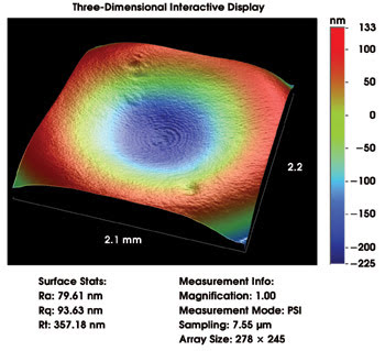
Figure 1. An aspheric element with a best-fit sphere subtracted from the final result shows large differences between the two. Courtesy of Veeco Instruments.
When measuring highly sloped and curved surfaces with an optical profiler, light from the test surface does not follow the exact optical path of light from the reference surface. This optical path difference has traditionally been accounted for by mapping the residual error and subtracting it from the measurement of each part. New software allows a user to store a series of error maps taken from high-quality surfaces, and the software automatically subtracts these errors from subsequent measurements. This method maintains nanometer-level accuracy, even over very steep test surfaces.
Measuring larger steps
Diffractive elements and some silicon optics contain large surface steps that also prove challenging for optical measurement. Phase-shifting interferometry is limited to pixel-to-pixel height differences of less than approximately 160 nm, which is insufficient for measuring many free-form optics. Coherence-sensing techniques, such as vertical scanning interferometry, overcome this step height limitation but lack the accuracy of phase shifting.
A new technique developed by Veeco Instruments Inc. of Tucson, Ariz., combines phase and coherence information to produce measurements with subnanometer noise over many microns of vertical range. This method has been improved by the addition of an interferometric “reference signal” that tracks the scanner and adjusts for slight drifts that might occur during a series of stitched measurements. The combination of hardware and software enables high-fidelity characterization of surfaces with high steps or complex overall shape. An optical profiler analysis of a diffractive element measured with this technique captures the very fine surface roughness as well as the large surface steps (Figure 2).
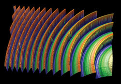
Figure 2. A diffractive element was measured using a combined phase-shifting and coherence-sensing technique. Courtesy of Glimmerglass.
Analyzing free-form surfaces
Once surface data has been obtained, data analysis software is required to relate the surface shape to the optic’s performance. Traditional Zernike analysis, typically used for spherical optics, is not meaningful for many aspheric designs. Instead, the most common method is to analyze the difference between the designed and the actual surfaces. Software has been developed to automatically subtract data taken from several widely used optical design software packages.
Alternatively, given the part’s aspheric coefficients, the software will automatically center and scale the theoretical data with respect to the actual data for proper subtraction. Once the difference is calculated, many analysis techniques can be performed on the result, including overall root-mean-square roughness, power-spectral density and pixel-by-pixel surface slope.
Other software techniques analyze the actual optic surface and calculate parameters such as the Strehl ratio, the point-spread function or the bidirectional reflectance distribution function to directly characterize its optical properties.
Data analysis of free-form optics requires highly accurate measurement hardware as well as flexible software. As these optics become even more prevalent, production-floor metrology for process control will become even more critical. The demands of increasingly complex designs and tighter tolerances will continue to drive improvements in interference microscopes that will make it possible for such elements to be employed in a greater variety of applications.
Meet the authors
Erik Novak is head of the research and development group for optical and industrial metrology products at Veeco Instruments Inc. in Tucson, Ariz.; e-mail: [email protected].
Mike Zecchino is a technologies writer for Veeco; e-mail: [email protected].