Ron Rekowski, Aerotech Inc.
No longer an exotic manufacturing application, laser welding is now a common production tool for processing pacemakers, defibrillators and other implantable medical devices. Applying the weld to the seams of these devices requires precise firing control to maintain a consistent overlap in the laser welding pulses. Also critical are positioning and velocity control while traversing the perimeter of the part, which is essential for a hermetic (sealed) weld seam. The laser’s focal point, power and pulse width, as well as the part’s position, must be tightly synchronized.
Traditional approaches to welding medical components have involved rotating the part and manipulating an X-Y-Z actuator to track movement along the seam and to keep the laser normal to the part surface. Engineers handle path planning for the axes off-line with a computer-aided manufacturing package that decomposes the linear and circular components of the part in Cartesian coordinates into small motion segments on the actuator.
In production, a technician further modifies the process to optimize performance because small radii in the part profile result in unacceptably large accelerations in the motion system. The resulting program is a compromise that limits the effective speed of the linear motion segments to ensure consistent results across the entire part.
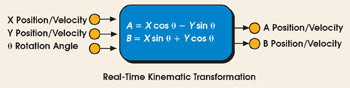
Figure 1. Real-time kinematic transformation reduces programming time and complexity and permits rapid changeover to alternate part profiles.
An alternative to off-line transformation is to run the transformation in real time on the control (Figure 1). Such kinematic transformation reduces programming complexity by shrinking the program size by as much as an order of magnitude. Part geometry of most pacemakers and defibrillators, for example, can be defined in as little as five to 10 program statements, unlike transformed output from a computer-aided manufacturing application that could contain 50 to 100 lines. Modifications to the program are more intuitive because each line in the motion program can be directly correlated to a feature on the part.
Programming in part coordinates also allows the application to take advantage of a controller’s path-planning functions, such as multiblock look-ahead (Figure 2). Welding speed can be reduced automatically to minimize high accelerations generated as a function of small radii features on the part. The resulting optimized velocity and position profiles are then run through the kinematics in real time to generate motion for the physical axes.
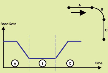
Figure 2. Multiblock look-ahead capability in an Aerotech A3200 controller can optimize velocity and position profiles.
The optimized velocity and position profile also can be used to directly trigger the laser firing. By monitoring the path displacement in real time, the laser can be pulsed at precise intervals along the surface of the part to maintain consistent weld spot overlap. The overlap is maintained even as the surface feed rate changes to react to the part geometry.
Flexible part alignment
Running the kinematics in real time also allows engineers to specify the point of rotation of the workpiece at run time. Programs generated with a postprocessor must assume a fixed point of rotation, requiring special attention to the fixturing of the part to ensure that the actual point of rotation coincides with the coordinates of the point used to generate the motion profile. Any variation between these two coordinates can adversely affect weld quality by varying the focal point and, therefore, the laser power.
To fully realize all of these process improvements, however, the controller must interface to high-performance linear and rotary positioning stages. The stages must be able to convert the optimized motion commands of the controller into highly accurate motion of the part.
The profiles of the devices being laser welded sometimes have small part geometries that can result in large accelerations, even at relatively slow welding speeds. Likewise, the configuration of the actuator implies that there will be numerous reversals of direction on multiple axes as the part rotates through the welding process.
Direct-drive linear and rotary stages provide the necessary performance with none of the backlash, wind-up or stiction common with ball-screw-driven stages. Faster acceleration also can translate to higher welding speeds and reduced part-processing time.
Direct-coupled linear and rotary feedback devices improve part accuracy by measuring actual stage displacement, unlike screw-based feedback devices, which measure motor displacement. Direct-drive linear and rotary stages coupled with brushless linear/rotary motor technology provide nearly maintenance-free operation in a 24/7 working environment. Direct-drive stages also tend to have a smaller footprint. This reduction in size can be critical in medical seam-welding applications, which often take place in a glove-box enclosure.
In essence, coupling real-time kinematics with direct-drive positioning systems not only can boost the efficiency of laser seam-welding systems, but also can help lower the total cost of ownership.
Meet the author
Ron Rekowski is product marketing manager of the Advanced Automation Div. of Aerotech Inc. in Pittsburgh; e-mail: [email protected].