The rapid transition from cathode-ray tubes to microdisplays is driving rapid change in processes and products.
Matt Mazzuchi and John Corless, JDS Uniphase
The television market is changing channels. The rapid increase in availability of high-definition video content through network broadcasting and other means is driving a corresponding increase in demand for high-definition televisions to display that content.
Plasma and flat-screen liquid crystal display (LCD) televisions have excellent picture quality, but those that consumers find to be affordable are limited by screen sizes of less than 50 in. diagonally. Leading the way in larger screen sizes are new microdisplay-based rear-projection televisions that deliver stunning images at reasonable cost.
Microdisplay advantages
Rear-projection TV based on cathode-ray tubes (CRTs) provides full-color images by combining the light from a CRT for each of the primary colors — red, green and blue. Then each corresponding image is magnified and projected onto a screen (see figure), and they are not brought together until the light reaches the screen. The form factor of this type of TV set is dictated by the bulkiness of the CRT.
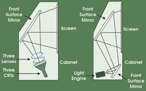
The major differences between the setup for a CRT-based rear-projection TV (left) and that of a microdisplay-based rear-projection TV (right) are the optical engine technology, the front surface mirrors and the projection TV screens.
In microdisplay-based rear-projection TV, a light engine replaces the red, green and blue CRTs. A high-pressure mercury lamp generates light, which passes through color-management optics. That light is imaged onto a microdisplay device, such as an LCD or liquid-crystal-on-silicon display. A projection lens sends the image onto the back of the rear-projection TV screen. Typical magnification of the light from the microdisplay device to the screen is between 50 and 100 times.
High-definition TVs equipped with microdisplay light engines provide many advantages over conventional designs. They not only offer superior-quality high-definition images, but also big advantages in form factor, such as a much shallower box depth and significantly reduced weight.
The challenges
Consumer acceptance of the new microdisplay TVs has been overwhelming. The image quality is excellent, and the availability of high-definition content is growing at a rapid pace. The price-to-performance ratio keeps improving to the point where the demand last year for these microdisplay sets outstripped the supply of key rear-projection TV components such as screens, lamps and related optics.
The demand for rear-projection high-definition TV is exploding at the same time that the technical challenges in making those microdisplay sets are beginning to be fully understood. The lack of standardization in design approaches has led to a variety of conditions that must be met to ensure acceptable image quality on the screen.
Major components
Microdisplay rear-projection TVs, like their data projector cousins, require high-pressure lamps to generate the light. Lamps vary in wattage, arc gap and reflector styles, all of which affect optical designs. High-pressure mercury lamps typically are used as the light source for these displays and, because of impressive advances that have been made in this technology over the past several years, these components can now offer upward of 6000 hours of lifetime before requiring replacement by the consumer.
Getting the longest lifetime from a lamp is achieved primarily by finding the proper thermal environment for the bulb. Different lamps require different operating conditions. In general, each engine configuration will require new thermal optimization to ensure that they provide the proper lifetime performance. The lack of standardization makes it necessary to customize each lamp-cooling solution for each application.
Projection lenses are important components that both magnify and transfer the image from the microdisplay to the TV screen. Variables that affect the lens design include the microdisplay resolution and size, the optical path length from light engine to screen (referred to as throw distance), the f ratio (or f number) and the magnification. Projection lenses are frequently custom-designed for one particular cabinet/light engine combination.
Reducing mirror defects
In CRT-based rear-projection TVs, defects on the front surface mirror will not affect all three colors in the same location. Different bundles of light for a given point on the screen travel different optical paths in the cabinet, depending on their color. With microdisplays, on the other hand, all three colors are “converged” in the optical engine and white light is projected onto the screen. Therefore, a defect can have a much different impact on the front-of-screen performance for this technology, as all three colors will experience a defect in the same location on the mirror, causing noticeable defects on the screen.
The common mirror-defect-size tolerance for microdisplay sets is 100 to 300 μm on a component that typically measures several square feet in area. Acceptable specifications for microdisplay TVs depend on the engine design and cabinet layout, which vary by manufacturer. To address this problem, JDS Uniphase in Santa Rosa, Calif., developed technologies for these large mirrors to maintain the premium high-definition TV image quality.
The need for standards
The recent stellar growth in microdisplay-based rear-projection TVs is the result of broad efforts in the industry among many players, including screen suppliers, engine makers, optical component manufacturers, high-pressure lamp makers and the key microdisplay panel providers. Much of the heavy lifting has already been done to establish the business and its related supply chain, and to make enabling innovations in rear-projection TV set form factors. However, to continue these efforts and allow the industry to realize its full potential for growth, standardization of major elements is critical.
Meet the authors
Matt Mazzuchi is a product line manager for DLP products at JDS Uniphase-Lasers in Santa Rosa, Calif.; e-mail: [email protected].
John Corless is an engineering manager at JDS Uniphase-Lasers; e-mail: [email protected].
A New LCOS
With the growth in high-performance displays, supporting technologies are evolving at a rapid rate. Brillian Corp. of Tempe, Ariz., which develops high-definition televisions, has taken the liquid-crystal-on-silicon (LCOS) technology a step further.
LCOS is a 10-year-old technology that sandwiches liquid crystal between a glass plate and a silicon chip. According to Rainer Kuhn, senior director of sales and marketing, Brillian’s proprietary, patent-pending Gen II LCOS offers a contrast ratio as high as 2000 to 1, compared with the 800 to 1 achieved with the company’s previous version. On the optics side, the Gen II LCOS’ reflectance value has increased from 65 percent to as much as 70 percent. And the time response is now just 10 ms, compared with 16 ms with Gen I.
Kuhn indicated that manufacturing challenges are fewer with the Gen II because the Gen I’s architecture was replaced with an inorganic alignment layer. He said that the applications that will benefit from this technology are in any area where high contrast is desirable, such as flight simulators, and monocular and binocular headsets.
Anne L. Fischer