The next step beyond interoperability: Integrating optical design with CAD software enables virtual prototyping and information sharing throughout the design and production process.
Jean-Baptiste Haumonte and Jean-Claude Venturino, Optis
The worlds of computer-aided design (CAD), manufacturing and engineering have gradually welcomed simulation tools enabling the modeling of mechanics, machining, thermal effects, motion dynamics, vibration and acoustic phenomena, but until now optical simulation has been left to evolve independently. And yet this information-sharing opportunity gives engineers the chance to participate in a broad collaborative work space, considerably raising their level of knowledge about the system they are designing.
They can produce unlimited virtual prototypes that enable them to simulate multiple “what if” scenarios and that optimize their final design choices. The integration of simulation capabilities into the CAD world brings creativity and knowledge for the whole community.
It was high time that optics joined this concurrent process to help simulate the entire optical system in its end-product context.
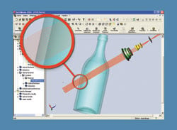
Figure 1. A glass bottle is inserted within an optical sequence for innovative industrial vision simulation.
Optical software was limited because optics was not connected to other areas of product design. Interactions between mechanics and optics, for instance, had never been possible in the same software. Most traditional simulation software was stand-alone, and although some enabled data export and import, transfer errors were a problem. More importantly, the process lacked intuitiveness. Altering something in the optics meant that the mechanics had to be rethought from the beginning.
Product design possibilities were also limited because traditional software development didn’t keep up with advances in industrial production capabilities. For example, although industrial machines have allowed the production of free-shape optical components for 30 years, product designs have not followed suit because traditional optical design programs could simulate only spherical and aspherical lenses.
The solution was to integrate optical design in CAD software. This also presented the opportunity to drastically improve the possibilities of optical design by incorporating it into a global product process, involving concurrent design, information sharing and virtual prototyping up to final production. The aim was to allow the optical engineer to collaborate with the mechanical engineers, stylists, ergonomists and others in a single-window collaborative work space.
Eliminating time lost
An objective for software designers at Optis was to eliminate time lost in the back and forth between optical and mechanical software. The data-transfer phase between stand-alone optical and mechanical software is not only laborious, but also highly subject to errors. These errors can be generated by the difference in design conventions among software; for example, where a dimension is measured from and to, or by the loss of precision when numbers are rounded off.
A real technical challenge for integration was how to best exploit industry capabilities and enhance the impact of optics in the global process. In the past, optical software had been subjected to several levels of CAD integration.
The first level is mainly present in most available software. Stand-alone optical software can treat systems with sequential or nonsequential simulation: Photometry, aberration and radiometry results; ray tracing; spot diagrams; and modulation transfer or point spread functions are obtained without any interaction with other physical parameters.
This means that calculation and optimization are done independent of the surrounding mechanics, for instance, and cannot be automatically updated with global systems changes. After having designed and optically validated systems, optical engineers can deliver their design to mechanical engineers with CAD import/export capabilities, but cannot directly rework it and generally cannot interact with other departments.
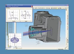
Figure 2. Treatment of optical rays as mechanical parts maximizes optomechanical interaction with direct measurements.
Integration of mechanical tools into optical design software can be considered as the second degree of integration. With these tools, optical engineers benefit from direct optomechanical design capabilities. The mechanical environment is developed around the optics. Data import and export are still required. Designers cannot use specific CAD software tools and remain isolated from the CAD world, which minimizes interactions between optics and other disciplines.
The third level of integration was achieved by Optis in 2001 by providing nonsequential lighting simulation with luminance, illuminance, intensity, colorimetry, radiometry simulation, analysis and optimization capabilities in its OptisWorks software. The advantage of this is that designers can calculate optical performances directly in CAD. The main challenge was to ensure accuracy of optical components in the mechanical software because, for the time being, part definition in CAD reaches micron and not nanometer dimensions.
That is why Optis has developed specific integrated tools providing more than 100-nm definition for parts of the optical sequence.
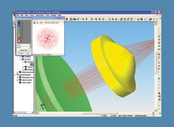
Figure 3. A CAD spline tool allows designers to freely create optical shapes for miniaturized systems.
The fourth level of integration is available in OptisWorks optical design software and gives SolidWorks engineers access to CAD design tools such as “Spline,” which means that they can, for the first time, test free shapes such as nonuniform rational B-splines. These so-called NURBs are industry-standard tools for the representation and design of geometry. Engineers are also able to test progressive lenses in their sequences. This fourth level is a technological revolution for designers.
Ray propagation in CAD software can be carried out sequentially or nonsequentially. Sequential propagation is better adapted to the design, analysis and optimization of imaging systems. The integration of optical design in CAD software gives the user access to optical features, including paraxial calculations, aberrations, spot diagrams and wavefronts, while nonsequential propagation can be used to analyze the propagation of rays in complex 3-D systems. Surfaces and materials are defined to take into account scattering or absorption on optical elements or mechanical assemblies. Applications include stray-light analysis, illumination analysis from an extended source or colorimetric analysis.
One challenge is to link the optical design with the mechanical design process. Typically, the ray trace is transferred from the optical design software to the CAD program. But once this is done, the ray trace becomes a dead geometry. It’s not parametric, so the ray vector can’t be used to define or constrain solid-model features and assembly elements. The integration of optical design in CAD software helps the engineer create a layout sketch that can be used for this purpose. When optical properties are modified, it becomes possible to create another layout sketch corresponding to the new situation to add constraints with solid models.
Another advantage of integrating optical design in CAD software is that users can benefit directly from the wide possibilities of the CAD modeler. Thus, free-form shapes can be defined with the modeler, and optical performances of these shapes can be rigorously evaluated. One typical application is the miniaturization of optical systems. Telecentric systems could be replaced by nonsymmetric systems with free-form shapes. This innovation allows designers to move away from accepted product shapes and sizes.
Adaptive optics
Free-form shapes also are required, for example, in the optimization process of backlighting. This feature, which already is integrated in most optical design stand-alone software, can be made easier in CAD software with parametric tools and constraints between these shapes. Another application of free-form shapes is adaptive optics, which is mainly used to correct phase aberrations in astronomy or laser propagation. A typical adaptive optical system is based on deformable mirrors, which can be modified easily in CAD software to quickly evaluate their optical performances.
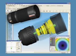
Figure 4. Optics and mechanics design in the same software opens up an efficient collaborative work space.
This complete interaction between optical components and mechanical assemblies is an advantage during the optimization process. In fact, when mechanical assemblies are built around and from optical elements, the modification of an optical dimension can update the shape directly. The optical optimization has a direct effect on the mechanical shape. The opposite also is true: Modifying the mechanical shape can update the optical components. This means that the optimization can be done on more parameters.
Meet the authors
Jean-Baptiste Haumonte is OptisWorks product marketing manager (e-mail: [email protected]) and Jean-Claude Venturino is product developer (e-mail: [email protected]) at Optis in Toulon, France.