Although lasers range from quantum-dot to football-field size and utilize materials from free electrons to solids, the underlying operating principles are always the same. This article provides the basic information about how and why lasers work.
Coherent Inc.
Over 60 years have passed since the first demonstration of a laser in 1960. After the initial spark of interest, lasers were for a while categorized as “a solution waiting for a problem,” but bit by bit, the range of their applications has expanded to encompass fields as diverse as DNA sequencing, consumer electronics manufacturing, or freezing the motion of electrons around atoms. Most of these applications simply would not have been possible without lasers. To grasp the relevance of lasers in physics, it is enough to note that no other man-made sources can generate pulses (of any type) as short as laser pulses — now below to 10−16 s — or tools to measure absolute frequencies with an accuracy of ~10−15! Industrial manufacturing, microelectronics, and biomedical and instrumentation applications serviced by lasers are incredibly diverse and rely on unique capabilities, like producing features below the limit of light diffraction, modifying materials in their bulk while leaving the surface unaffected, or trapping and moving individual particles in mid-air.
All light sources convert input energy into light. In the case of the laser, the input, or pump, energy can take many forms, the two most common being optical and electrical. For optical pumping, the energy source may be a lamp or, more commonly, another laser. Electrical pumping can be via a DC current (as in laser diodes), an electrical discharge (noble gas lasers and excimer lasers), or a radio-frequency discharge (most CO2 lasers).
In a conventional (incoherent) light source like a lightbulb, an LED, or a star, each atom excited by input pump energy randomly emits a single photon according to a given statistical probability. This produces radiation in all directions with a spread of wavelengths and no interrelationships among individual photons. This is called spontaneous emission.
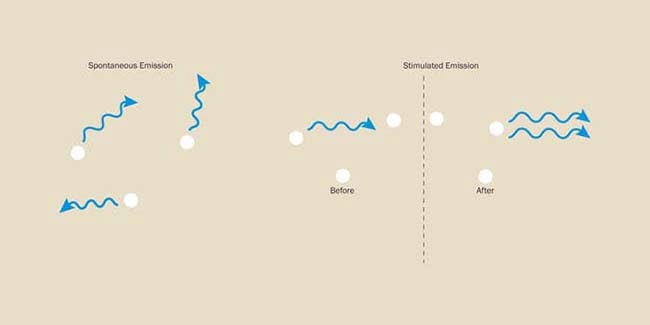
Figure 1. Spontaneous emission is a random process, whereas stimulated emission produces photons with identical properties.
Einstein predicted that excited atoms also could convert stored energy into light by a process called stimulated emission. This process typically starts with an excited atom first producing a photon by spontaneous emission. When this photon reaches another excited atom, the interaction stimulates that atom to emit a second photon (Figure 1). This process has two important characteristics. First, it is multiplicative — one photon becomes two. If these two photons interact with two other excited atoms, this will yield a total of four photons, and so forth. Second and most importantly, these two photons have identical properties: wavelength, direction, phase, and polarization. This ability to “amplify” light in the presence of a sufficient number of excited atoms leads to “optical gain” that is the basis of the laser operation and justifies its acronym of Light Amplification (by) Stimulated Emission (of) Radiation. A wide range of solid, liquid, and gas-phase materials have been discovered that exhibit gain under appropriate pumping conditions.
The laser cavity
The laser cavity, or resonator, is at the heart of the system. A single transit through a collection of excited atoms or molecules is sufficient to initiate laser action in some high-gain devices such as excimer lasers; however, for most lasers, it is necessary to further enhance the gain with multiple passes through the laser medium. This is implemented along an optical axis defined by a set of cavity mirrors that produce feedback (Figure 2). The lasing medium (a crystal, a semiconductor, or gas enclosed in an appropriate confinement structure) is placed along the optical axis of the resonator. This unique axis with very high optical gain becomes also the direction of propagation of the laser beam. A somewhat different example of a uniquely long (and flexible!) gain axis is the fiber laser.
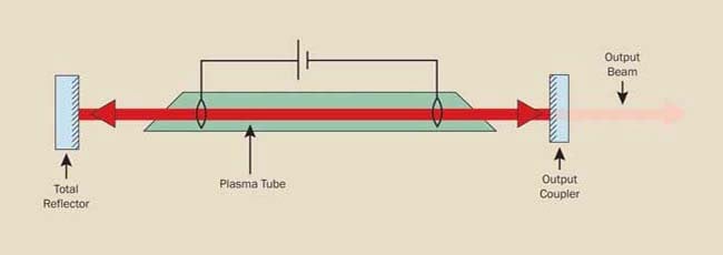
Figure 2. In the prototypical gas laser, the gain medium has a long, thin cylindrical shape. The cavity is defined by two mirrors. One is partially reflecting and allows the output beam to escape.
The simplest cavity is defined by two mirrors facing each other — a total reflector and a partial reflector whose reflectance can vary between 30% and close to 100%. Light bounces back and forth between these mirrors, gaining intensity with each pass through the gain medium. Photons that are spontaneously emitted in directions other than the axis are simply lost and do not contribute to the laser operation. As laser light is amplified, some of the light escapes the cavity, or oscillator, through the partial reflector (output coupler); however, at equilibrium (the so-called “steady state” or “continuous wave”), these “optical losses” are perfectly compensated by the optical gain experienced in the successive round trip of the photons inside the cavity. The output of the laser is exactly the part of the beam transmitted by the output coupler. In an ideal laser, all the photons in the output beam are identical, resulting in perfect directionality and monochromaticity. This determines the unique coherence and brightness of a laser source.
Monochromaticity — A photon’s energy determines its wavelength through the relationship E = hc/λ, where h is Planck’s constant, c is the speed of light, and λ is wavelength. An ideal laser would emit all photons with exactly the same energy, and thus the same wavelength, and it would be perfectly monochromatic. Many applications are dependent on monochromaticity. For example, in telecommunications, several lasers at slightly offset wavelengths can transmit in parallel streams of pulses down the same optical fiber without crosstalk. Real lasers are not perfectly monochromatic because several broadening mechanisms widen the frequency (and energy) of the emitted photons. For example, free-running YAG lasers can have linewidths of tens of gigahertz, while stabilized diode-pumped YAG lasers can have a linewidth <1 kHz. The best known of these broadening mechanisms is the Doppler broadening, determined by the distribution of speeds in the collection of atoms making up active gas mediums.
Coherence — Besides sharing the same wavelength, the photons that make up an ideal laser beam are all in phase (Figure 3), or “coherent,” resulting in an electric field that propagates with a uniform wavefront. The ideal representation is a plane wave that propagates with a flat wavefront along a given direction and where each plane perpendicular to this direction experiences the same electric and magnetic field amplitude and phase at a given time. When two waves with such characteristics interact, they create interference patterns, as in Young’s experiment. Real laser beams somewhat deviate from this ideal behavior, but they are still the sources that best approximate an ideal coherent plane wave, and they enable a host of applications that rely on optical interference. For example, the surface of precision lenses and mirrors is measured using laser interferometers, and so are the minute variations in the interference patterns of miles-long interferometers used to chase and detect gravitational waves.
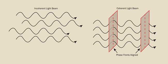
Figure 3. Laser light differs from conventional light in that all the lightwaves are in phase with each other.
Brightness (or, more correctly, radiance) — The most strikingly visible difference between lasers and conventional light sources is that all the emitted light travels in the same direction as an intense beam. Radiance is defined as the amount of light leaving the source per unit of surface area and unit of solid angle. A star like the sun emits a large amount of radiation from a unit of surface area, but this is emitted in many different directions. On the contrary, a laser beam is highly directional, with the result that its brightness is much more intense than the sun’s as experienced on the Earth’s surface. For this reason, just 5 mW of power from a laser pointer is more “blinding” (and dangerous) for the eye than direct sunlight.
Because of its high radiance, a laser beam can be projected over great distances or focused to a very small spot. Well-designed lasers produce a beam of light that will expand (“diverge”) only by the minimum amount prescribed by the laws of diffraction. For example, diffraction imposes that the minimum spot that can be produced by a laser beam is equal to about its wavelength.
Continuous-wave lasers
Lasers can be divided into three main categories: continuous wave (CW), pulsed, and ultrafast.
As their name suggests, continuous-wave lasers produce a continuous, uninterrupted beam of light, ideally with a very stable output power. The exact wavelength(s) or line(s) at which this occurs is determined by the characteristics of the laser medium. For example, CO2 molecules readily lase at 10.6 µm, while neodymium-based crystals (like YAG or vanadate) produce wavelengths in the range between 1047 and 1064 nm. Each laser wavelength is associated with a linewidth, which depends on several factors: the gain bandwidth of the lasing medium and the design of the optical resonator, which may include elements to purposely narrow the linewidth, like filters or etalons.
If a laser can simultaneously produce different lines, the first step in determining the operating wavelength is to use cavity mirrors that are highly reflective only at the desired wavelength. The low reflectivity of the mirrors at all the other lines will prevent these from reaching the threshold for laser action. However, even a single laser line actually covers a range of wavelengths. For example, laser diodes produce light over a wavelength range of several nanometers corresponding to their “gain bandwidth.”
The specific wavelengths of the output beam within this gain bandwidth are determined by the longitudinal modes of the cavity. Figure 4 shows the behavior of a two-mirror cavity, the most basic design. To sustain gain as light travels back and forth between the mirrors, the waves must remain in phase and “reproduce” their wave pattern, which means that the cavity round-trip distance must be an exact multiple of the wavelength
Nλ = 2 × Cavity Length,
where λ is the laser wavelength and N is an integer called the mode number. This is usually a very large integer, since the wavelength of light is so much smaller than a typical cavity length. In a high-power laser diode, for example, the IR output wavelength is 0.808 μm, yet the cavity length may be 1 mm, so that even in a very small laser resonator, N is ~2500. Wavelengths that satisfy this resonance equation are called longitudinal cavity modes. The actual output wavelengths of the laser will correspond to the cavity modes that fall within the gain bandwidth, as shown in Figure 4 (bottom). This regime is called multilongitudinal-mode operation. Using the example of the high-power laser diode, the spacing between adjacent longitudinal modes is
W~150 GHz (equivalent to ~0.3 nm in wavelength difference).
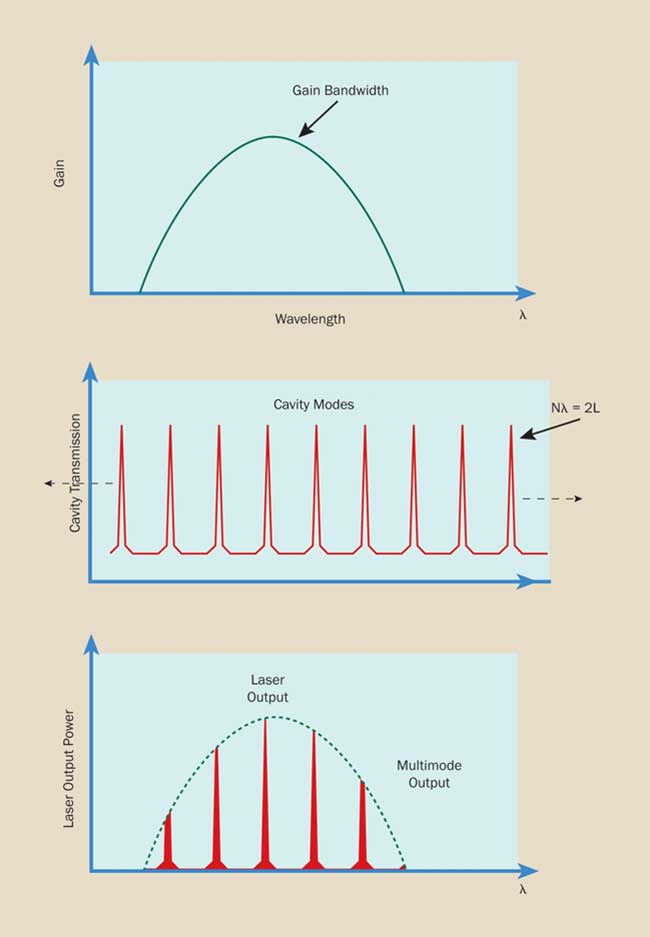
Figure 4. A resonant cavity supports only modes that meet the resonance
condition, Nλ = 2 × cavity length. The output of a CW laser is defined
by the overlap of the gain bandwidth and these resonant cavity modes.
If the laser diode operates on a 3-nm gain line, about 10 longitudinal modes, spanning 3 nm, will be able to oscillate. The resonator design also controls the so-called transverse modes, responsible for the intensity distribution on the plane perpendicular to the beam direction. The ideal laser beam has a radially symmetric cross section: The intensity is greatest in the center and tails off at the edges, following a Gaussian profile. This is called the TEM00 or fundamental output mode. Lasers can produce also many other TEM modes, a few of which are shown in Figure 5. Usually a round aperture placed inside the cavity is used to force the laser to operate in the fundamental mode. In multitransverse-mode operation, many modes are present at the same time, often resulting in a profile that appears to be Gaussian but in reality has degraded properties (higher divergence and lower radiance). Often the quality of a laser beam is specified using the M2 (M squared) parameter. For example, a YAG laser operating exclusively in the TEM00 mode has M2 = 1, while multimode laser diodes have an M2 of hundreds. Different transverse modes also have slightly different frequencies; however, this difference is much smaller than the difference between adjacent longitudinal modes (~1 MHz compared with approximately hundreds of megahertz to hundreds of gigahertz).
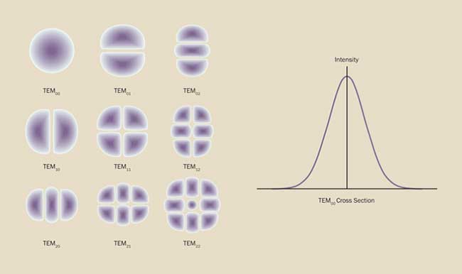
Figure 5. Lasers can emit any number of transverse modes, of which the TEM00 usually is most desirable.
A laser that produces multiple longitudinal modes has a limited coherence — different wavelengths cannot stay in phase over extended distances. Applications such as holography, which demand excellent coherence, benefit from using a single-longitudinal-mode laser. For some laser types with a narrow gain bandwidth, single-mode output is achieved with a very short resonant cavity; this makes the mode spacing larger than the gain bandwidth, and only one mode lases. Generally, though, a filtering element that preferentially passes only one mode is inserted into the cavity. The most common type of filter is called an etalon. Using a number of sophisticated design enhancements, it is possible to restrict the linewidth of a laser to less than 1 kHz, useful for scientific interferometric applications.
Some solid-state lasers have extremely broad bandwidths that extend to hundreds of nanometers. The most common example is the Ti:sapphire laser. Rather than being a disadvantage, this broad bandwidth enables the design of tunable and ultrafast (femtosecond and picosecond pulse width) lasers. Designing a tunable CW laser involves including an extra filtering element in the cavity — usually a birefringent (or Lyot) filter. A birefringent filter does two things: It narrows the bandwidth and, by rotating the filter, allows smooth tuning. This same type of filter is also used as a factory-set tool to lock the wavelength at a precise value, when broad-bandwidth lasers need to be preset at a specific application-dependent wavelength. This is typically the case with optically pumped semiconductor lasers (OPSLs) that can be set at the desired wavelength within their 5- to 10-nm operating range.
Most applications of CW lasers require that the power be as stable as possible over long time periods (hours or weeks), as well as over short time durations (microseconds), depending on the specific application. To ensure this stability also in the presence of varying environmental situations like temperature, vibration, and the aging of the laser itself, microprocessor control loops are implemented. For example, a diode-pumped Nd laser will have servos to adjust temperature and output power of the pump diodes to maintain stable output power from the resonator. In addition, other servos may control the perfect alignment of the resonator mirrors.
Pulsed lasers
Some materials — like excited dimers (or “excimers”) of a noble gas with a halogen, such as ArF and XeCl — sustain laser action for only a brief period of tens of nanoseconds. Other lasers, like Nd or Yb diode-pumped solid-state (DPSS) lasers, lend themselves to be operated both in CW or pulsed operation. Other lasers, like laser diodes or OPSLs, are not suitable at all for pulsed operations. Within this context, we define as “pulsed” laser devices that produce pulses of 0.5 to 500 ns. This regime is useful for time-resolved scientific experiments but especially for a vast range of manufacturing processes related to ablation or some other type of nonthermal materials modification. The most important characteristic of a nanosecond-pulsed laser is the capability to “store” and release energy very rapidly; i.e., on a nanosecond scale so that the laser output can achieve tens of kilowatts to megawatts of peak power. It is precisely this high peak power that enables the ablative processing of materials. In addition, the high peak power enables a number of so-called optical nonlinear processes, like harmonic generation and optical parametric amplification.
Operating a nanosecond-pulsed laser is substantially different from operating a CW laser. To build and produce each pulse, the light has time for very few round trips in the laser cavity, and the simple two-mirror cavity based on a partly transmissive mirror described so far cannot produce these energetic and short pulses. The key to producing these energetic pulses is storing energy from the pump in the atoms or molecules of the lasing medium by preventing the laser gain and the amplification process. Then, when the stored energy is at its maximum, lasing action is rapidly enabled: The stored energy results in an extremely high laser gain (amplification) that takes place during only a few round trips, during which a giant pulse builds up and gets coupled through the partly transmissive mirror. This regime is called Q-switched operation and can be conceptualized as a two-mirror cavity with an optical gate located between one of the mirrors and the laser medium (Figure 6). When the gate is closed and the laser medium is pumped, photons cannot circulate in the cavity, and the excitation of the atoms builds up; as soon as the gate is opened, photons start to build up via stimulated emission with a very large gain at each round trip; a fraction of them (~20% to 40%) get coupled by the partly transmissive mirror. The result is a pulse with a very sharp raising time and a slower falling time, with a typical duration of 1 to 200 ns. The pulse duration depends on several parameters: the type of gain medium and how much energy it can store, the cavity length, the repetition rate of the pulses and the pump energy, to mention the most important ones. Q-switched lasers commonly used in the industry can produce average powers up to tens or hundreds of watts and repetition rates as low as 10 Hz or as high as 300 kHz. Most industrial processes are in the tens-of-kilohertz to hundreds-of-kilohertz regime.
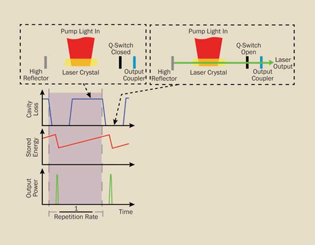
Figure 6. Schematic showing the operating principle of a Q-switch in a solid-state laser.
The actual Q-switch device is an acousto-optical modulator or an electro-optical modulator (EOM). Both use crystals where an applied electric field produces some perturbation of the optical properties of the crystal. In the case of acousto-optical modulators, the applied electric field is a radio-frequency voltage that produces a high-frequency sound wave in the crystal. This sound wave diffracts the photons from the laser and prevents laser amplification. EOMs instead use an applied high voltage that modifies the crystal refractive index and alters the polarization of the incoming light; an appropriate combination of polarization-sensitive optics can be placed in the cavity to only allow light of the altered polarization to circulate, leading to emission of a ms pulse when voltage is applied to the EOM.
Other types of lasers, such as excimer lasers, do not require a Q-switch to produce nanosecond pulses but rather rely on a transient pump pulse: Excimer laser pulses are produced by exciting the noble gas/halogen mixture with a powerful and short electric discharge. Ti:sapphire lasers can also produce nanosecond pulses if they are pumped with a nanosecond pulse of green light produced by a frequency-doubled, Q-switched YAG laser. This method is called gain switching because the cavity gain rather than the cavity loss is directly changed.
Apart from a huge number of industrial applications, Q-switched lasers have important applications in scientific research. One is pumping of Ti:sapphire ultrafast amplifiers (described in the following section) by using the frequency-doubled (green) output of a Q-switched Nd:YAG or Nd:YLF at 1-10 kHz. Another one is using the YAG or YLF laser to produce energies per pulse in the joule range at 1-100 Hz. These lasers are often used with nonlinear optical generators that can produce tunable wavelengths in the UV, visible, and IR region, enabling time- and wavelength-resolved studies. Nowadays most YAG or YLF lasers operating at >1 kHz are diode-pumped, while high-energy 10- to 100-Hz systems require pumping with a flashlamp because diodes are not suitable for producing high-energy output pulses.
For some scientific applications, it may be desirable to have a narrow-linewidth Q-switched laser. In some cases, this can be accomplished using a combination of optical gratings and etalons; in other cases, the laser can be “seeded” with a low-power CW or Q-switched narrow-linewidth laser that is easier to control than the higher-power stage. This approach, called “injection seeding,” uses a MOPA (master oscillator, power amplifier), conceptually splitting the linewidth selection and the high-power generation into two stages that are optimally designed for the two purposes.
Ultrafast lasers
Ultrafast lasers are generally defined as lasers that produce pulses in the range of 5 fs to 100 ps (1 femtosecond = 10−15 seconds). If a laser is able to oscillate in many longitudinal modes, such short pulses can be produced with the so-called mode-locking technique. With this technique, the modes are locked in phase (mode-locking regime) and their coherent interference causes the intracavity optical field to collapse into a single pulse traveling back and forth in the laser cavity. Every time the pulse reaches the output mirror, part of it is coupled out and available.
Physics shows that the more modes that interfere, the shorter the pulse duration (Figure 7). Since larger lasing bandwidths support a larger number of oscillating modes, the pulse duration is inversely proportional to the bandwidth of the laser gain material. In the absence of dispersion, these pulses are time-bandwidth limited, i.e., have the shortest possible length for a given bandwidth.
Ultrafast pulses are highly useful in research; thanks to the short pulse duration and high peak power, the advent of femtosecond lasers in the 1990s enabled groundbreaking research leading to Nobel prizes for femtochemistry (pump-probe spectroscopy) and optical comb generation. Femtosecond lasers have also enabled multiphoton excitation (MPE) techniques that deliver three-dimensional imaging of live tissue. MPE is now widely used in several areas of biological research, most notably neuroscience.
Many important applications require the ultrafast pulses to be amplified using one of several methods such as regenerative amplification or a master oscillator power amplifier (MOPA) approach. Pulse amplification usually requires a reduction in repetition rate, so a pulse-picker selects the oscillator pulses to be amplified in one or more amplifier stages. In the case of femtosecond lasers, the high peak power of the amplified pulses can damage the laser optics. For this reason, the amplification is usually preceded by stretching the pulse (chirping) to 50 to 200 ps. The amplified pulse is then re-compressed to the fs domain. This is commonly referred to as chirped pulse amplification, or CPA.
In scientific research, amplified ultrafast pulses are used for a wide array of applications. These include photochemistry, pump-probe spectroscopy, terahertz (THz) generation and creating accelerated electrons and other small charged particles. The pulses can also drive nonlinear generation of extreme-UV light with pulse widths of tens of attoseconds.
In industrial applications, amplified ultrafast pulses are increasingly used in materials processing applications that require ablation or materials modification without any residual thermal effect and/or on a submicron spatial scale. Examples include thin-film patterning in the production of flat panel displays. Ultrafast lasers are also increasingly used to cut the toughened glass for touchscreens, using a process called filamentation cutting that cannot be performed with other lasers. This method produces unmatched edge quality and can create curved shapes and cutouts.
Ultrafast laser materials
Until recently, scientific ultrafast lasers have mainly relied on titanium:sapphire (Ti:sapphire) because of its large bandwidth and broad tuning range; turnkey commercial Ti:sapphire lasers can deliver pulses as short as 6 fs. Ti:sapphire lasers are typically pumped using a green-wavelength CW pump laser. Typical repetition rates of Ti:sapphire oscillators are 50 to 100 MHz, and peak powers as high as several hundred kilowatts.
The most common CPA systems based on Ti:sapphire operate at 1 to 10 kHz with the amplifier stages energized by nanosecond green lasers. Ti:sapphire CPA systems are unique in their ability to produce pulse energies of several millijoules with pulse widths as short as 20 fs. Custom CPA systems based on Ti:sapphire can produce even petawatt peak powers.
Industrial ultrafast lasers typically need high repetition rates and high power in order to sustain economically viable throughput in the application. Until recently, most of these have been MOPA systems based on Nd-doped bulk materials (e.g., YVO4, YAG, or glass). These lasers and amplifiers are well-proven to provide the requisite combination of power and industrial reliability. However, the smaller the gain bandwidth of Nd means that they are limited to the 10-ps regime. Their high peak power and high repetition rates find applicability in precision micromachining applications, particularly for thin films and/or for tough materials like chemically strengthened glass, using the filamentation method just mentioned.
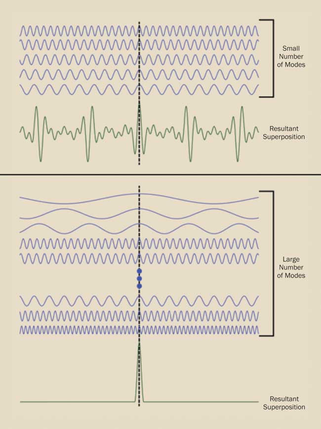
Figure 7. When a very large number of laser modes that all have a “zero” in the same position interfere, the resultant superposition is an extremely narrow pulse.
In the past 10 years, femtosecond lasers and amplifiers using ytterbium (Yb) have become available to meet evolving market needs in both the scientific and industrial sectors. An example is the Monaco series of Yb-based MOPAs from Coherent.
Yb-doped materials combine to some extent the advantages of Ti:sapphire scientific lasers and Nd-based industrial lasers. For scientific research, the gain bandwidth of Yb means oscillator pulses can be as short as 50 fs, which is more than adequate for many applications, particularly in MPE microscopy. Unlike Ti:sapphire, Yb can be directly diode-pumped and used in a fiber format, enabling more scalable performance than bulk gain materials that are often limited by cooling and thermal lensing issues. This means that Yb-fiber MOPA-type amplifiers can deliver flexible repetition rates as high as tens of MHz. When used to pump optical parametric devices, the resulting output is fully tunable from UV to mid-IR wavelengths, providing advantages for applications such as spectroscopy of advanced materials, or functional biological imaging. It should be noted that for scientific applications needing extremely short (<50 fs) pulse widths and/or high pulse energies, Ti:sapphire currently remains the preferred gain material, and both media will co-exist for the foreseeable future.
For industrial applications, the main attraction of Yb-fiber amplifiers is the combination of high peak power and high average power in the femtosecond regime, unlike Nd systems with picosecond pulse widths. Femtosecond laser pulses have two advantages over picosecond pulses for materials processing. First, the femtosecond pulse durations are an order of magnitude shorter than the time it takes to establish thermal conduction in the material, unlike with nanosecond pulses. Second, the short pulses and nonlinear interaction means that fs pulses can deliver even better edge quality and precision than ps pulses. As a result, Yb-fiber amplifiers are rapidly finding applications in micromachining of mixed layered substrates (e.g., polyimide on glass) as found in electronics and displays.
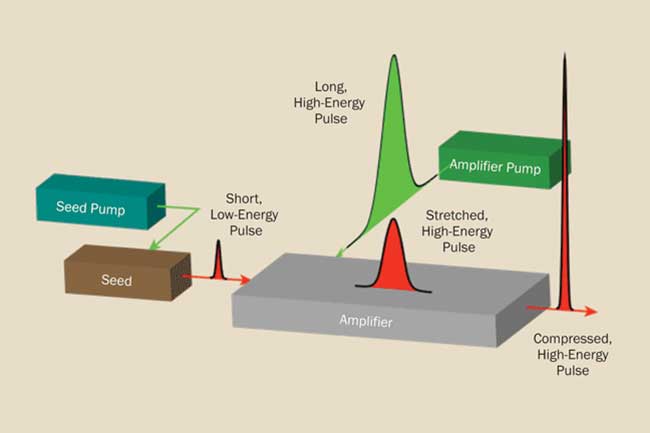
Figure 8. The basic elements and operation of a chirped pulse amplifier (CPA).
Frequency doubling and harmonic generation
Even with the broad choice of commercially available lasers, it is not always possible to find one that exactly matches the wavelength required by a specific application. Ti:sapphire lasers are broadly tunable, but in most cases, they are too complex for industrial applications and unable to reach the all-important UV region of the spectrum. OPSLs are simple and can be designed at many wavelengths in the 920- to 1160-nm region but are not suited for pulsed operation. To achieve the desired wavelength in just about any regime of operation — CW, pulsed, or ultrafast — the processes of harmonic frequency conversion and parametric generation provide wavelength flexibility when used in conjunction with the lasers described so far. All these processes are related and are called nonlinear optical processes since their strength depends nonlinearly on the laser peak power. That is, they are proportional to the square, third, or higher power of the laser peak power.
In simple terms, when an intense and/or tightly focused laser beam passes through a suitable crystal, its oscillating electric field interacts with the electrons of the crystal in several ways. One of these mechanisms distorts the electron cloud in the crystal, thereby polarizing the atoms at a frequency that is the same as that of the laser beam, but also at a frequency that is its double (nonlinear polarization). This frequency corresponds to a wavelength that is half that of the incoming laser. The nonlinear polarization is much smaller than the linear term, but it depends on the square of the laser peak power, therefore increasing more strongly in the presence of an intense laser pulse. It generates an optical field at double the frequency of the original laser beam, with the result that part of the incoming laser power will be converted to half the original wavelength (second-harmonic generation (SHG) or frequency doubling) (Figure 9). Since energy has to be conserved, any gain in the SHG beam is traded for a decrease in power of the original beam. In some cases, it is possible to achieve an almost total conversion of the original (“fundamental”) beam into its second harmonic. Common crystals for SHG are BBO, LBO, and KDP. The most common example of SHG is the conversion of a Nd-based laser IR output at 1064 nm into a green output at 532 nm (green), constituting the most popular visible wavelength, used ubiquitously to pump Ti:sapphire lasers.
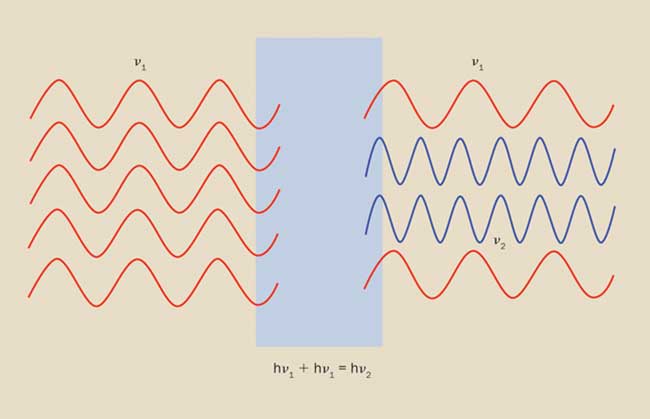
Figure 9. Basic functioning of a second-harmonic generating crystal.
Efficient SHG can be achieved only under a condition called “phase matching.” Under most conditions, the light at the new frequency would be reconverted to the original frequency and lost or simply not added in phase to create any sizable power. This difficulty is overcome by choosing a crystal temperature and orientation that create the so-called phase-matching condition where the phase velocities of the fundamental and second-harmonic light are the same. This happens by choosing a specific direction of propagation (usually a function of temperature and wavelength) in the crystal such that the two waves propagate at the same velocity.
Extensions of the SHG process are third-harmonic generation (THG), where the wavelength at one-third the incoming wavelength is created by the interaction of an SHG beam with its fundamental; and fourth-harmonic generation (FHG), where the SHG beam is frequency-doubled again. All of these harmonic processes can be generalized as frequency-mixing, where two coherent beams at different wavelengths are mixed to produce sum-frequency and difference-frequency generation (SFG and DFG, respectively).
Harmonic generation can be applied to CW, pulsed, and ultrafast lasers, greatly expanding the range of available wavelengths. Pulsed or ultrafast lasers have enough peak power (kilowatt range) to achieve relatively high conversion efficiency in a single pass through the harmonic crystal. On the other hand, CW lasers usually do not produce sufficient power for efficient harmonic generation, so that the power in the crystal has to be enhanced by putting the nonlinear crystal inside the laser cavity (“intracavity doubling”), or building a cavity ad hoc around the crystal (“resonant doubling”) that matches the modes of the original CW laser cavity.
Optical parametric generation
In the sum frequency mixing process described in the previous section, two photons at different frequencies interact to produce a single photon at a frequency that is the sum of the two initial frequencies. The opposite process is also possible: A single photon interacts with a suitable crystal and disappears, creating two photons of lower and different (called “nondegenerate”) energies. This process, called optical parametric generation, is useful because it results in the generation of two new tunable wavelengths, bound solely by the conservation of energy and momentum, and by the nonlinear crystal refractive indices n:
νp = νs + νi
1/(npλp) = 1/(nsλs) + 1/(niλi)
The subscripts p, s, and i refer to the pump wavelength and to the two new wavelengths that are called (for historical reasons) “signal” and “idler,” with the signal wavelengths being the shorter of the two and both being longer than the pump wavelength. Phase matching takes place when the refractive indices of the three wavelengths np, ns, and np satisfy the above momentum conservation equation in the crystal. This can be accomplished by changing the temperature or angle of the crystal, or the pump wavelength (if the pump laser is tunable) so that phase matching takes place at the desired signal or idler wavelength.
While the wavelength of an SHG beam is unambiguously determined by the pump wavelength, the OPG process can generate an infinite set of wavelength pairs. Amplification of the desired wavelength pair requires not only phase matching in the crystal but also “jump starting” the process from the noise of the statistical distribution of wavelength pairs. This is exactly what happens in an optical parametric oscillator (OPO) or an optical parametric amplifier (OPA), both advanced laser accessories able to produce tunable outputs anywhere from the mid-UV to the mid-IR.
In an OPO, the signal and possibly the pump are resonated in a laser-like cavity, where the desired signal wavelength starts from the noise (random distribution of signal/idler pairs) and is amplified by passing through the crystal properly phase-matched for that wavelength at the same time as the pump during each round trip (Figure 10). In an OPA, a sapphire or YAG disk is pumped to produce a relatively bright beam of white light that, as the name suggests, contains all the wavelengths of the visible and near-IR spectrum. The unique wavelength pair that is phase-matched in the OPA crystal will then be amplified when the crystal is pumped by the pump laser.
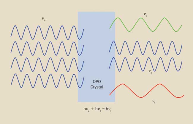
Figure 10. An optical parametric oscillator (OPO) converts an input photon into two photons having lower energy, and which conserve the energy and momentum of the input.
Nano-, pico-, and femtosecond OPOs are complex devices that are implemented in conjunction with pulsed and ultrafast pump lasers. CW OPOs are equally, if not more, complex. OPAs are easier to design and build but require a more energetic pump to produce the white light and one-pass amplification in the crystal. For this reason, they are pumped by CPA pico- or femtosecond amplifiers producing at least several microjoules. The addition to an OPA/OPO of one or more stages of harmonic generations and mixing yields a range of wavelengths that can cover 200 nm to 20 µm.
Common laser types
For many years, the most common CW laser was the helium neon laser, or HeNe. These low-power lasers (a few milliwatts) use an electric discharge to create a low-pressure plasma in a glass tube; nearly all emit in the red at 633 nm. In recent years, the majority of HeNe applications have switched to visible laser diodes. Typical applications include barcode readers, alignment tasks in the construction and lumber industries, and a host of sighting and pointing applications ranging from medical surgery to high-energy physics.
In fact, the laser diode has become by far the most common laser type, with truly massive use throughout telecommunications and data storage (e.g., DVDs, CDs). In a laser diode, current flow creates charge carriers (electrons and holes) in a p-n junction. These combine and emit light through stimulated emission. Laser diodes are available as single emitters with powers up to tens of watts, and as monolithic linear bars with numerous individual emitters. These bars can be assembled into 2D arrays with total output powers in the kilowatt range. They are used in both CW and pulsed operation for so-called direct diode applications. But even more importantly, laser diodes now underpin many other types of lasers, where they are used as optical pumps that perform the initial electrical-to-optical power conversion.
For example, higher-power visible and UV CW applications were originally supported by argon-ion and krypton-ion lasers. Based on a plasma discharge tube operating at high current, these gas-phase lasers are large and inefficient, generating a large amount of heat that must be actively dissipated. The tube also has a finite lifetime and thus represents a costly consumable. In most former applications, the ion laser emitting at blue or green wavelengths was displaced by DPSS lasers. Here, the gain medium is a neodymium-doped crystal (usually Nd:YVO4) pumped by one or more laser diodes. The near-IR fundamental at 1064 nm is then converted to green 532-nm output with the use of an intracavity doubling crystal.
The DPSS laser, in turn, has been challenged by several newer technologies, with the OPSL the most successful of these. Here the gain medium is a large-area semiconductor laser that is pumped by one or more laser diodes. The OPSL offers numerous advantages, most notably wavelength and power scalability. Specifically, these lasers can be designed to operate at virtually any visible wavelength, at last freeing applications from the restrictions of limited legacy-wavelength choices (i.e., 488 and 514 nm from argon-ion lasers and 532 nm from frequency-doubled YAG lasers). Indeed, OPSLs represent a paradigm shift in lasers because they can be designed for the needs of the application instead of vice versa.
OPSL is now a leading technology in low-power bioinstrumentation applications, most notably at 488 nm; the power scalability and inherent low noise of OPSL technology is now seeing multiwatt green and yellow OPSLs moving strongly into other applications, including scientific research, forensics, ophthalmology, and light shows.
While YVO4 and other neodymium crystal hosts lend themselves to operation in CW, Q-switched and mode-locked operations, laser diodes, OPSL, and ion lasers do not support Q-switched operation and are virtually not used in mode-locked regime.
At longer wavelengths, carbon dioxide (CO2) lasers, which use plasma discharge technology, emit in the mid-infrared around 10 µm. Most are CW or pseudo-CW, with commercial output powers from a few watts to several kilowatts. A similar technology is the carbon monoxide (CO) laser, which was originally developed in the 1960s, but only made truly practical for industrial use in 2015. CO lasers emit in the 5 to 6 µm spectral range. This shorter wavelength, mid-infrared output offers two important advantages for some applications as compared to CO2 lasers. The first is that many metals, films, polymers, PCB dielectrics, ceramics, and composites exhibit significantly different absorption at the shorter wavelength, which can sometimes be exploited to advantage. The second is that they can be focused to smaller spot sizes due to diffraction, which scales linearly with wavelength. Together, these characteristics enable the CO laser to deliver superior results in some glass processing, film cutting, and ceramic scribing applications.
Another important technology is the fiber laser, which can be operated in CW, Q-switched, and mode-locked formats and typically emits at about 1 μm (when the fiber is ytterbium-doped). In a fiber laser, the resonator is formed by a large mode area, double-clad optical fiber (with the outer cladding containing the dopant) and fiber Bragg gratings for resonator mirrors. This is pumped from each end by a series of diode lasers, whose outputs are fiber-coupled into the gain fiber.
The fiber laser offers several important advantages. The first is that the output is naturally fiber-delivered, which makes it easy to couple into many laser machine tools and to integrate the laser with robotic delivery systems. Next, fiber laser beam quality is sufficient to couple it into small fibers, allowing the beam to be focused to small spots in order to obtain the high power densities required for metal welding, cutting, and other industrial processes. Fiber laser architecture also lends itself to power scaling. A single set of pumps and gain fiber can typically produce output powers of up to multiple kilowatts, but it is also possible to use fiber combiners to enable power scaling, achieving output powers exceeding 10 kW. Finally, fiber lasers have high wallplug efficiency (the conversion of input electrical energy into laser light) compared to CO2 and solid-state lasers, and can also have low maintenance requirements. This lowers cost of ownership.
Nd:YVO4, Yb:YAG, CO2, Yb-doped fiber, and direct diode lasers are the workhorses of industrial laser applications. Direct diode lasers, in particular, offer the lowest cost per watt of any industrial laser type, as well as the lowest operating costs, due to their high electrical efficiency. Direct-diode lasers predominantly service low-brightness applications, such as heat treating, cladding, and some welding applications. On the downside, high-power laser diodes or arrays cannot deliver anything close to the diffraction-limited beam provided by other laser types.
The advent of slab-discharge technology has allowed the size-to-power ratio of CO2 lasers to be greatly scaled down, increasing their utility in subkilowatt applications. Low-cost waveguide designs also support a healthy market for CO2 lasers with powers in the tens of watts, primarily in marking and engraving applications.
Over the past decade, high-power fiber lasers (>1 kW) have come to dominate metal cutting applications in the 4- to 6-mm thickness range because they typically offer excellent results, together with lower maintenance costs than CO2 lasers of similar power. Furthermore, near-infrared fiber lasers are advantageous when cutting certain metals, such as copper, aluminum, and brass, which are difficult to cut with CO2 because of their high reflectivity in the far-infrared.
CO2 lasers continue to be used for even thicker materials, but this is mostly because the processes have been optimized for this laser and manufacturers are slow to change a production process that works well. However, this is likely to change over time. CO2 lasers at 1 kW and below are still utilized in some thinner metal (2 to 4 mm) cutting applications. And CO2 lasers remain the first choice when both metals and nonmetals must be processed. This is because their longer wavelength is well absorbed by a wide range of nonmetallic materials, including wood, paper, leather, cloth, plastics, and many other organics, while the near-infrared fiber laser output is not.
Nd:YAG can deliver the high peak power for materials processing applications such as metal welding and cutting. In these heavy industrial applications, raw power is more important than beam quality, and for many years, these lasers were lamp-pumped. Today, these lasers have been mostly replaced by diode-pumped Yb-based fiber lasers and disk lasers, with output powers of up to 20 kW. Flashlamp pumped Nd:YAG, Er:YAG, and Cr:Tm:Ho:YAG are still being used in medical applications, where pulse energies in the joule range are required at repetition rates of tens of hertz. In this high energy operating regime, diode-pumping is not cost-effective.
Conversely, lower-power Q-switched DPSS lasers are mostly based on Nd:YVO4. These are usually optimized for high beam quality for micromachining and microstructuring applications with high repetition rates (up to 250 kHz) to support high throughput processes. They are available with powers up to tens of watts with a choice of near-IR (1064 nm), green (532 nm), or UV (355 nm) output. The UV is popular for producing small features in “delicate” materials because it can be focused to a small spot and minimizes peripheral thermal damage. Deep-UV (266 nm) versions are starting to be used in some applications, but their relatively high cost and the need for specialty beam delivery optics causes many potential applications to rely instead on 355-nm lasers optimized for short pulse duration, which can produce similar results in many materials.
Excimers represent another important pulsed laser technology. They can produce several discrete wavelengths throughout the UV; depending on the gas combination, emission ranges from 157 to 348 nm. The deep-UV line at 193 nm is the most widely used source for lithography processes in the semiconductor industry. The 308-nm wavelength is used for annealing silicon in high-performance displays. The same wavelength is also key to generating a unique long-wear surface on the cylinder liners of high-performance diesel engines. And finally, excimers have a unique ability to produce high pulse energies — up to one joule per pulse. This enables direct writing of low-cost electronic circuits for applications such as medical disposables.
Ultrafast lasers for scientific applications are dominated by Ti:sapphire, as already described. Ultrafast lasers are also a fast-growing technology for micromachining and other high-precision materials processing applications. While there is some diversity in the form and construction of commercially available industrial ultrafast lasers, they all utilize a certain basic configuration. Specifically, a passively mode-locked oscillator is used to generate output at the pulse widths of about a couple of ps or shorter that are necessary to drive photoablation. However, most mode-locked oscillators produce relatively low energy pulses (in the nanojoule range) at repetition rates in the tens of megahertz. Best results for micromachining are achieved when the pulse-to-pulse overlap is in the range of 50% to 70%. In other words, the beam deflection mechanism moves the beam about one-third of the beam diameter before the arrival of the next ultrafast pulse. Consequently, a repetition rate in the range of tens of megahertz is too high to be used with existing scanning technology, so a pulse picker selects a fraction of these pulses. The energy of these pulses is then boosted in an amplifier to produce the final output.
Most commercial picosecond and femtosecond products are based on one of the following architectures:
• A fiber laser oscillator followed by fiber-based preamplifiers and a fiber- or rod-fiber amplifier.
• A fiber laser oscillator followed by fiber-based preamplifiers and one or more bulk amplifiers.
• A diode-pumped solid-state oscillator followed by bulk amplifiers.
The all-fiber (oscillator and amplifier) approach has the advantage of being relatively low cost and holds the potential of being robust. The big negative is that nonlinearities and thermal effects in the fiber amplifier limit the maximum per-pulse energy and average output power than can be attained to about 100 µJ and 100 W, respectively (at a sub-ps pulse width and using CPA). This level of pulse energy can cater to most micromachining applications today.
To achieve higher pulse energies and higher output power that are required for some present and many future applications, a fiber oscillator can be mated with a bulk amplifier. If the gain in the bulk amplifier is low, as is the case for Yb-doped rod- or disk-type amplifiers, a regenerative amplifier is used. In a regenerative amplifier, a pulse undergoes a large number of passes (up to 150) to extract the energy stored in the amplifier medium. The ability to extract energy from low-gain amplifiers allows the use of large beam areas to achieve very high pulse energies of hundreds of mJ and output powers in the multi-kW range.
The third approach is to use a fiber oscillator in combination with fiber-based preamplifiers and bulk, diode-pumped solid-state amplifiers with high gain, usually with Nd:YVO4 (for 10 ps pulses) or Yb:YAG (for sub-ps pulses) as the gain medium. These geometries have demonstrated output powers in the multi-100-W range, and, in the case of Yb:YAG, up to the kW-level.
And finally, many other types of niche and exotic lasers exist that are beyond the coverage of this overview article. Examples include Raman lasers used in telecommunications, quantum cascade lasers used in some gas-sensing applications, and chemical lasers, which tend to be limited to military programs.