Optimizing vehicular flat panel displays depends greatly on developing standards for measuring the ambient light that strikes them.
Silviu Pala, Denso International America
The display that a driver sees inside a vehicle differs vastly from one car model to the next. Display standards — in terms of luminance, legibility, contrast, font size and more — are of concern to automakers.
A group with the Society of Automotive Engineers (SAE), in collaboration with the International Standard Organization, the National Institute of Standards and Technology (NIST) and the Society for Information Display, has been working since 1998 on the Standard Metrology for Vehicular Displays — Optical Performance (SAE J1757/1) for display legibility. The goal is to provide methods to determine the optical performance of vehicular displays in all typical lighting conditions.
Efforts to develop this standard began in 1995 when the automotive division of United Technologies Corp. of Dearborn, which was later sold to Lear Corp. of Southfield, both in Michigan, tested the first automotive display prototype based on electroluminescent technology. The prototype was measured and evaluated indoors, and the optical performance showed very high contrast resulting from the emissive nature of the electroluminescent display. The calculated contrast in daytime was acceptable for diffuse light.
The test was repeated outdoors on a sunny day, and it was difficult to tell when the display was on or off because of the glare from the sun and sky. Clearly, standards were needed and, in 1999, the SAE began official work to develop them. Three years later, SAE J1757/1 was released, and then updated in 2006.
There are many challenges to developing standards for vehicular displays: Ambient illumination from sun and sky must be accommodated in both typical and worst-case scenarios; the best light source for a display to counteract ambient light must be determined, as must the geometry that provides acceptable visibility of a display both in the laboratory and in a vehicle; and the cost of measurement equipment must be kept low and setup procedures kept as simple as possible so that automakers will widely adopt the tests.
In addition, novel test parameters, such as diffuse-haze and diffuse-lambertian, yield more complete information regarding the display surface. The most important of these is the “haze” reflection near the specular angle (Figures 1 and 3).
Some vehicular flat panel displays are given a surface treatment to reduce specular reflections. However, this creates a “haze component” near the specular component, which might have a wide angular spread (Figure 1). Usually, a driver can move his or her head to avoid the specular reflection, but it is difficult to do so to avoid both specular and haze. Besides haze properties of the vehicular flat panel display surface, there are haze properties of the light source; therefore, finding the proper one was a challenge.
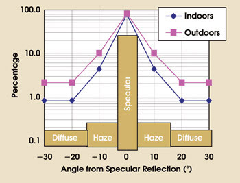
Figure 1. Reflections from a display surface were taken indoors using a sun gun and outdoors using ambient light from the sun and sky. Images reprinted with permission from SAE International.
Many light sources were evaluated, and the main problem was the haze created by the display surface and by the ambient light. White fluorescent light was eliminated as a choice because of its sharp spectral lines, which were not close enough to daylight, according to the International Commission on Illumination’s technical report “Solar Spectral Irradiance.” Other sources of light were eliminated because their color temperature for white was either too high or not high enough.
Using laserlike collimated sources generated a different contrast ratio, with the results depending on the location of the sharp spot. The testers determined that it was better to use a light source that puts a wide spotlight on the measurement surface. Initially, they used an illuminated spot several times larger than the measurement spot, but they ultimately increased the illuminated surface to allow for a better approximation of the sun and sky.
This provided the evaluators with test conditions that had closer to real-life illumination representing the worst case. Lamps comprising hydrargyrum (mercury) medium-arc iodide — a halide — and providing a wide illumination spot gave the best correlation of indoor and outdoor measurements despite their “spiky” spectral appearance.
High ambient illumination
The easy way to measure ambient light in a car is to use a luxmeter. However, these devices are bulky, preventing them from getting close enough to the measurement spot. In addition, small variations in their placement can create wide variations in luminance readings because variables such as the multiple reflections from vehicle parts, windows and the driver’s clothes result in nonuniform ambient light inside a car.
In testing, the SAE group used diffuse white reflective paint on a hard, opaque material and placed it atop the display area to be measured. A spectrophotometer placed where the driver’s head would be measured both ambient illumination (from the white reflective surface) and luminance for on and off pixels to obtain a contrast ratio (Figure 2).
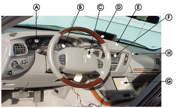
Figure 2. An in-vehicle measurement example shows ambient illumination. Measurements are acquired from the location of the driver’s head.
(Using this method violates the separation principle between “illumination E,” measured in lux, and “luminance L,” measured in candela per square meter. The maximum error between real value and measured value estimated by the NIST was 8 percent but, because the measurement is performed using the same geometry and because the display setup is the same, the relative error is very small despite potential high variation in absolute values on cumulative measurement errors.)
In conclusion, the luminance value as a result of illumination is given by Li = S + DL + DH, where S, DL and DH are specular, diffuse-lambertian and diffuse-haze components, respectively.
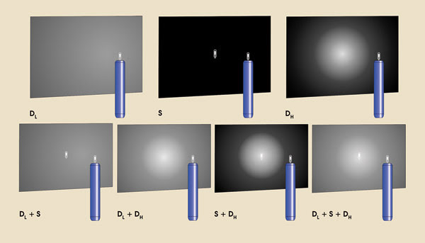
Figure 3. Reflections from the surface of a vehicular flat panel display are shown with diffuse-lambertian (DL), diffuse-haze (DH), specular (S) and combinations thereof.
The typical setup
The value Li is strongly dependent on the angle of measurement, so it was important to define the value for θp (the photometer’s measurement angle) (Figure 3). The values were defined for both the car definition (from driver’s head/eye ellipse space toward the display), and for the default situation (when the car’s geometry is unknown). The line from the center of the in-vehicle display to the midpoint of the eye-ellipse was labeled the central critical specular line. The line that is symmetrical with respect to the normal direction of the display is called the central critical specular light direction (Figure 4). Ambient light following this direction has a significant effect on display legibility.
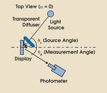
Figure 4. The top view of an in-vehicle measurement setup is shown.
The most challenging aspect of testing was determining the location and facing direction of the light from the sun gun (Figures 4 and 5). The SAE standard defines the vehicle’s critical specular surface (with respect to the display) as the intersection between the critical light source cone and the windows.
The next steps include determining and reducing the measurement uncertainty resulting from equipment calibration (also taking into consideration potential country-specific variations). The testers also must now resolve legibility issues related to color contrast (not just luminance contrast), including how to measure it and how to determine the meaning of the measurement value with respect to legibility. This is challenging because human vision has multiple variables.
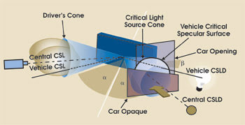
Figure 5. The critical specular light (CSL) and measurement setup are depicted. CSLD = critical specular light source direction.
The progress of display technology and its penetration into automotive applications will require a better, more refined way of defining and measuring legibility in high-ambient illumination.
Meet the author
Silviu Pala is a senior manager in Denso International America’s engineering division in Southfield, Mich.; e-mail: [email protected].