Combining photonics with the technology of micro- and nanofluidics opens the door to many exciting applications.
David Erickson, Cornell University, Changhuei Yang, California Institute of Technology, and Demetri Psaltis, Ecole Polytechnique Fédérale de Lausanne
For centuries, the components in optical systems have been made from a variety of glasses and metals. More recently, however, they have been created from plastic and semiconductor materials. In other words, optical materials in general are solid in nature. Though prominent examples of fluid materials in optical systems exist (e.g., liquid crystals, dye lasers and liquid mirror telescopes), by comparison, they are not used extensively.
The development of modern micro- and nanofluidics began in earnest about 15 years ago with the fabrication of microchip-based capillary electrophoresis systems and mass spectrometers. Since that time, the field has exploded to the point where microfluidic devices now can sort thousands of cells per minute, can perform highly parallel chemical synthesis with ease or can screen complex samples for large numbers of biological pathogens.
The ability of microfluidic systems to handle this broad array of tasks so efficiently is largely because the flow within them is fundamentally more controllable than it is within macroscopic systems.
A number of research groups have begun to develop modern-day versions of fluid-based optical systems incorporating micro- and nanofluidic technology. Over the past two or three years, these efforts have matured into a new research field that has come to be known as “optofluidics.” In this article, we introduce, largely by way of example, this field. To do this, we begin by reviewing the advantages of macroscopic fluid-based optical systems and then introduce three examples of how these classical systems are being reinvented through the incorporation of microfluidic functionality.
Macroscale optics
Consider the three prominent examples of fluid optics already mentioned: liquid crystals, dye lasers and liquid mirror telescopes. Liquid crystals are used extensively in displays and spatial light modulators. The relative ease with which they change macroscopic optical properties through microscopic rearrangement of their molecules in the presence of relatively low electric fields results from the fact that they are suspended in a liquid medium and, thus, have very little resistance to physical reorientation.
In solids, where physical reorientation is impossible, it is difficult to obtain such a broad range of optical properties (e.g., refractive index) from a single material. This example also highlights a key difference between solid- and liquid-based systems. Generally, solid-based systems can be made to respond quickly, whereas liquid-based systems are better at actuating large property changes.
This also is exemplified in another classic fluid-based optical system, the dye laser. In place of a solid lasing medium, a dye laser typically employs a rapid jet of dye-doped fluid. One advantage of using liquids in such a system is that the lasing wavelength can be tuned broadly over the visible spectrum by swapping in other dyes with various emissive properties.
Our last example, liquid mirror telescopes, generally consists of a highly reflective metallic fluid medium (such as mercury) placed in a shallow pan and spun at an appropriate speed to create a parabolic surface profile.
Because of the combination of centrifugal force and surface tension, the resulting curved surface is optically smooth and is an excellent reflective focusing element. The University of British Columbia’s Large Zenith Telescope has a diameter of 6 m and is one of the world’s larger optical telescopes (Figure 1).
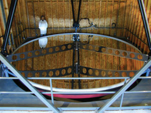
Figure 1. The University of British Columbia’s Large Zenith Telescope has a 6-m aperture, making it the third-largest optical telescope in North America. The rotating liquid mirror, weighing approximately 3 tons, is the largest ever built. The rotational speed of the bowl containing the mercury controls the shape of the lens and can be controlled to within one part per million. Courtesy of Dr. Paul Hickson, University of British Columbia.
Liquid telescope on moon?
A key advantage of a liquid mirror telescope is its cost, which is about 1 percent that of a conventional mirror. In addition, scaling up a liquid mirror is an easier proposition than scaling up a conventional mirror. The recent discussion of placing a liquid mirror telescope on the moon is motivated by yet another advantage of a fluid-based system — it will be far easier to transport the metallic liquid and to “fluidically assemble” the mirror than it will be to transport a large and unwieldy conventional telescope.
These largely macroscopic fluid-based optical systems showcase some of the advantages of using fluid in millimeters-to-meters-scale optical systems. The maturing microfluidic discipline prompts the question of whether the combination of optics and microfluidics likewise can yield better microdevices and can engender novel microsystems. The term “optofluidics” (in this context) was coined in 2003 at California Institute of Technology in Pasadena to describe this new research field, which has seen rapid development over the past four years. As an indication, a Google search of the term “optofluidic” returns thousands of hits today as compared with fewer than five just four years ago.
Clearly defining “optofluidics” requires first appreciating the confluence of scale and properties that current microfluidics shares with optics. Microfluidics describes the research field focused on the motion of liquids and gases in small channels to serve a number of purposes, ranging from pathogen detection to electronic cooling. Microfluidic systems are fabricated using subtle variations on traditional semiconductor lithographic techniques and are made from a vast array of materials, including silicon, glasses, plastics and soft elastomers.
With these techniques and materials, fluidic channels from as small as 50 nm to well above 100 μm can be made. Importantly, this range of microfluidic scales spans from much smaller than the wavelength of visible and infrared light to much larger. The dynamic nature of microfluidics allows one to build on-chip valves and pumps that can swap liquids in and out with vast ranges in linear optical properties, nonlinear optical properties and gain. As an example, Table 1 compares the linear refractive index tunability that is available through optofluidics (expressed as Δn/n) with that from a variety of materials.
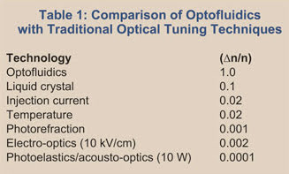
Table 1. The linear refractive index tunability (expressed as Δn/n) is shown for a variety of materials, including optofluidics.
Broadly speaking, most optofluidic devices under development involve the fabrication of specialized architectures; they also are designed for a particular application and make use of the adaptive nature of microfluidics to provide a unique functionality that cannot be achieved with a solid structure.
Recently, we exploited the feature size and spatial localizability of nanofluidic structures along with the high refractive index of liquids to take the first steps toward creating tunable photonic crystal circuits.1 To create these structures, we built a combined microfluidic/nanofluidic device in a soft elastomer called PDMS (polydimethylsiloxane) and fused it with a silicon-on-insulator photonic crystal structure (Figure 2). The flexibility of a soft elastomer such as PDMS allows it to conform to the underlying topography to prevent leaking.
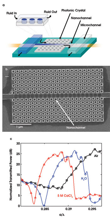
Figure 2. Nanofluidics can be used as a mechanism to tune photonic crystal circuits. The integration architecture for combining silicon nanophotonics with elastomeric nanofluidics is shown in (a). A scanning electron micrograph of a planar photonic crystal after removal of a nanofluidic network illustrates single row addressability (b). In (c), the tunability of photonic crystal bandgap is demonstrated by changing the fluids in the nanochannel from (b). Three cases are demonstrated: air (n = 1.0), distilled water (n = 1.33) and a 5-mol/l solution of calcium chloride (n = 1.44).
Our fluidic device had a microfluidic network that delivered fluids to the nanochannels overlying the photonic crystal (Figure 2a). In this case, the nanochannels were about 300 nm wide and 150 nm tall. In the device in Figure 2a, fluid flowed into the nanochannel, which was positioned relative to the photonic crystal so that a selected row of holes could be filled with liquid.
To illustrate the precision with which we could target a specific region of the photonic crystal, we allowed the fluidic system to dry after the experiment and permitted the salts in liquid solution to precipitate. The dark region along the central row of holes in the scanning electron micrograph in Figure 2b is where the salts precipitated. As can be seen, only the central row of holes is addressed, and there is almost no leakage into adjacent portions of the crystal. By dynamically switching the fluid in the holes from distilled water (refractive index = 1.33) to a 5-M solution of CaCl2 (refractive index = 1.44), we demonstrated shifting of the transmission window, creating a fluidically tunable photonic crystal waveguide.
Lasers and lenses
Optofluidic lasers are a natural extension of the conventional dye laser. Microfluidic technology holds the promise of being used for low-cost, compact and widely tunable laser systems. Although it is technically feasible to attempt to build a laser resonator using high-finesse mirrors in a microfluidic device, the relative ease of creating tiny features in microfluidics points to easier alternatives.
The distributed feedback optofluidic laser reported by Li et al is an excellent example of such an alternate laser design.2 This laser consists of a PDMS-based microfluidic channel, in which an array of regularly spaced PDMS posts is placed along the channel length. Laser dye then is flowed through the channel to serve as the gain medium. As shown in Figure 3, the device is optically pumped from above. The post array sets up a tightly confined resonant optical feedback within the channel and provides the optical feedback required for lasing.
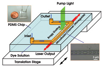
Figure 3. The lower inset is an optical micrograph of the central phase-shifted region of the laser cavity of a tunable optofluidic distributed feedback dye laser chip. A Bragg grating with a 3080-nm period is embedded in a 3-mm-wide microfluidic channel. The larger PDMS post (center) introduces a 15 π phase shift. The movement of the translation stage deforms the chip, which causes the grating period to change.
This optofluidic laser can be tuned in two simple ways. First, the dye medium can be swapped out and/or the pump laser changed for a big shift in the lasing wavelength. Second, the soft PDMS material can be stretched and compressed to alter the periodicity of the post array. This provides a way to fine-tune the laser.
Microfluidic optical lenses are another fundamental optical element for which incorporation of microfluidic functionality has proved useful. The advantages of these systems are similar to those described for the liquid mirror telescope. The laminar (nonturbulent) nature of microfluidic flow allows the creation of very smooth, almost “flaw free” interfaces that are impervious to damage. In contrast to solid systems, interfaces in optofluidic lenses can be physically manipulated from convex to concave or any shape in between through simple adjustment of the fluidic inputs.
One of the first microfluidics-based optical lenses was developed by Philips Research Eindhoven in the Netherlands and first published in 2004.3 This device comprised a cylindrical cell with oil floating on water. To create the adaptable lens, the Philips team utilized an effect called electrowetting to change the shape of the interface between the oil and water from a concave shape to a convex one simply by applying a small voltage.
A number of other successful variants on the technique have been developed, including a pressure-actuated membrane method and a hydrogel-based version. All these devices allow large adjustment of focal length without moving any parts. However, these approaches focus light in the direction perpendicular to the microfluidic chip plane as opposed to within it, the latter of which would be more useful for lab-on-chip-type applications. This problem recently was solved by Mao et al, who developed the system shown in Figure 4.4 This device exploits the difference in centrifugal force applied to two streams of liquid of differing density as they flow through a curved microfluidic channel.
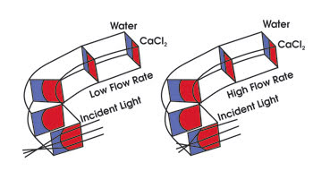
Figure 4. A planar optofluidic lens is formed by flowing two streams of liquid (water and a CaCl2 solution) beside each other in a microfluidic channel. The streams are sent around a smooth corner, and the centrifugal force on the higher-density CaCl2 solution causes it to push into the water stream as it rounds the corner, resulting in a curved interface exploited here as a lens. Increasing the flow rate increases the centrifugal force and, subsequently, the curvature of the interface. Image based on device presented by Mao et al.
In their specific implementation, a stream of water is flowed beside another stream comprising a highly concentrated solution of CaCl2. Because the flow is strongly laminar, the mixing between the two fluids is very slow, and the interface remains well-defined. As with all pressure-driven flows in a microchannel, the flow is faster in the middle of the channel than along the edges, so when the flow goes around a corner, the centrifugal force is higher in the middle.
This causes the higher-density solution to push in at the middle, forcing the lower-density water to push out near the top, forming the curved interface shown in Figure 4. Increasing the flow rate also serves to increase the local curvature. Because the CaCl2 has a higher refractive index than the water stream, this curved interface can be exploited to focus light channeled onto the microfluidic chip from an optical fiber.
Optofluidic devices have several advantages over their conventional counterparts — compactness, low cost, durability and flexibility. From a systems point of view, optofluidic devices offer yet another compelling advantage — easy integration. Whereas conventional optical systems generally consist of individual unconnected parts that must be carefully assembled and aligned, optofluidic devices can be designed and implemented onto the same platform from the start. For example, a conventional laser scanning system may consist of a laser, lenses and an actuation device that must be set and aligned with respect to each other. In principle, an equivalent optofluidic system can be implemented and fabricated as a whole on a single microfluidic platform. This can cut down dramatically on the system build time as well as on the risk of misalignment.
About the authors
David Erickson is the director of the Integrated Micro- and Nanofluidic Systems Lab and an assistant professor in the Sibley School of Mechanical and Aerospace Engineering at Cornell University in Ithaca, N.Y.; e-mail: [email protected].
Changhuei Yang is an assistant professor with the department of electrical engineering at California Institute of Technology in Pasadena; e-mail: [email protected].
Demetri Psaltis is dean of the School of Engineering, Ecole Polytechnique Fédérale de Lausanne in Switzerland; e-mail: [email protected].
References
1. D. Erickson et al (January 2006). Nanofluidic tuning of photonic crystal circuits. OPTICS LETTERS, pp. 59-61.
2. Z.Y. Li et al (Jan. 23, 2006). Single mode optofluidic distributed feedback dye laser. OPTICS EXPRESS, pp. 696-701.
3. S. Kuiper and B.H.W. Hendriks (Aug. 14, 2004). Variable-focus liquid lens for miniature cameras. APPLIED PHYSICS LETTERS, pp. 1128-1130.
4. X.L. Mao et al (2007). Hydrodynamically tunable optofluidic cylindrical microlens. LAB ON A CHIP, pp.