Lawrence Bogaert, Youri Meuret and Hugo Thienpont, Vrije Universiteit Brussel, Belgium
Most people were exposed to stereo displays through 3-D movies, which were the rage in the 1950s and now are enjoying a revival, thanks to the Imax process and animated films. Today, however, the technology has moved on to encompass a wide variety of applications beyond the entertainment venue. Stereo displays are being used as medical diagnostic tools, as an enabling technology for rapid prototyping of new products, for visualizing DNA and molecules, and for illustrating drill locations in oil exploration. Stereoscopic projection displays make it possible to visualize three-dimensional images.
In the stereoscopic display process, two images of a scene – corresponding to the views from the left and right eyes – are projected onto a screen. The viewer wears special eyeglasses so that each image is seen only by the eye for which it is intended. The horizontal disparity between the two images is interpreted by the brain as 3-D information.
Encoding left- and right-eye image information
Several methods exist to guide the image information to the correct eye. The oldest implementation – the one used in early 3-D movies – is the so-called anaglyph stereo method, which requires eyeglasses with two different filters. The left-eye image is seen through a red-coloured filter and the right-eye image through a cyan-coloured filter. One projector displays the image consisting of the two superimposed colours. The poor colour perception with this approach can be overcome with a pair of colour filters that transmit multiple narrow-wavelength bands. This is achieved via Infitec™ technology. The projector sequentially displays left- and right-eye images with a varying set of primary colours. For instance, the red-coloured left- and right-eye image components are modulated with a red that is orange-tinted and deeply saturated, respectively.
A second approach blocks the undesired image with a liquid crystal-based shutter incorporated into the eyeglasses, which are synchronized with the projection system via an infrared signal to close the right-eye shutter when the left-eye image is shown and vice versa. One projector can be used to sequentially display full-colour left- and right-eye images.
A third and last approach uses the polarization state of the images. This can be accomplished with two identical projectors dedicated to displaying the left- or right-eye image. Linear polarizer sheets are placed in front of both projection lenses to encode the images with orthogonal polarization states. Another implementation uses one projector and a linear polarizer combined with a liquid crystal-based device placed in front of the projection lens. This is called the ZScreen® technology. It sequentially converts the light output into left and right circularly polarized light. These systems require polarization-sensitive eyeglasses and a special screen that does not depolarize the projected images. Their efficiency is halved because the polarizer sheets block one polarization direction.
The two-projector polarization approach enables multiple viewers to see full-colour 3-D images displayed by normal-frame-rate projectors. Two projectors signify high cost, larger size and more power consumption. Also, the pixels of the two images must be precisely aligned on the screen, both projection lenses must be adjusted to scale the image equally, and both polarizer sheets must be aligned.
At Vrije Universiteit Brussel, a projection display that incorporates the functionality of both projectors and polarizer sheets into one optical engine has been developed and demonstrated at the department of applied physics and photonics. The system does not have the efficiency loss associated with the polarizer sheets in other polarization-based approaches and can use all colours of the spectrum efficiently.
System architecture
The optical engine uses reflection-type liquid crystal light modulators to create two independent light-processing paths simultaneously, generating two full-colour images with an orthogonal state of polarization. The system works by using four polarizing beamsplitters positioned such that their polarization-splitting surfaces form a cross shape, as shown in Figure 1. A first polarizing beamsplitter is used to split the unpolarized light from the illumination system into s- and p-polarized light that propagates toward a third and second polarizing beamsplitter, respectively. These are necessary to spatially separate the illumination and modulated light beam by the liquid crystal on silicon (LCOS) panels.
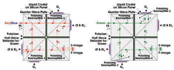
Figure 1. Shown is a schematic representation of the light-processing paths within the optical engine. Depicted on the left is modulation of the s- and p-polarized red and blue image components. The green image components are on the right.
Light modulated at the second polarizing beamsplitter contains the s-polarized image information, whereas the p-polarized image information originates from the third polarizing beamsplitter. Finally, a fourth polarizing beamsplitter recombines both images toward the projection lens. Polarizer sheets between the polarizing beamsplitters compensate for their limited extinction ratio. Quarter-wave plates are placed between the LCOS panels and the MacNeille polarizing beamsplitters to compensate the effect of skew-ray depolarization on the system contrast.
One LCOS light modulator can be colour-sequentially illuminated to create full-colour images. This is a cost-effective approach that is practical when a high-intensity discharge lamp is used in combination with a colour wheel. The projection display has been designed to operate with red, green and blue LEDs. These light sources enable compact and low-maintenance illumination systems with a large colour gamut.
In an approach using a single LCOS panel, each image frame is divided into three equal-length time intervals to modulate the image colour components with the three primary colours.
Because of this, a certain colour will limit the total light output for a projected image with a specific white point. For LED illumination, this is green. Therefore, a second LCOS panel is added to each light-processing path to continuously modulate the green image component. The other LCOS panel colour-sequentially modulates the red and blue image components. This modulation scheme maximizes the green light output and hence the total light output. It also decreases the colour breakup associated with colour-sequential modulation. The LCOS panels are positioned at different sides of the second and third polarizing beamsplitters. Because of this, it is necessary to rotate the state of polarization of the illumination and modulated light beam by 90° for green light compared with red and blue light. This is realized by adding wavelength-selective half-wave retarders between the polarizing beamsplitters.
The illumination system is designed to telecentrically illuminate the LCOS panels. This is necessary to avoid colour gradients induced by angle-sensitive components such as the MacNeille polarizing beamsplitters. The output of the LEDs is collimated using transparent compound parabolic concentrators with a square-shaped input and output. A lenslet integrator with microlenses is used to ensure uniform illumination of the light modulator despite possible nonuniformities at the output of the LED collimators.
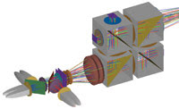
Figure 2. Shown is a design model of the optical engine with an LED-based illumination system implemented in ray tracing software (ASAP®).
The optical engine and illumination system have been designed, characterized and optimized using nonsequential ray-tracing software. A ray trace plot of the system is shown in Figure 2. A proof-of-concept demonstrator has been made of the entire stereoscopic projection display, as shown in Figure 3. When wearing linear polarization-sensitive eyeglasses, the viewer can perceive information in 3-D. The glasses do not permit tilted-head motion, however, because the polarizer in front of each eye would transmit part of the s- and p-polarized image. This can be solved by placing a quarter-wave retarder at the output of the projector that converts the images to a left and right circularly polarized state and by wearing circular polarization-sensitive eyeglasses. An example of a left- and right-eye view is shown in Figure 4. The projector can also be used to display 2-D images. For this, two identical images are modulated.
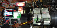
Figure 3. The prototype system using Osram Ostar® projection LEDs.
What does the future hold?
Polarization-based stereoscopic projection displays no longer require two separate projectors to modulate the left- and right-eye images. These can be simultaneously generated by one optical system that does not require any polarizers at the projector output. Besides images that can be visualized with eyeglasses in 3-D, the system can display images in 2-D without any mechanical adjustments, which increases its functionality. LEDs have proved to be a potential light source for small-screen stereoscopic projectors. How soon will LEDs be used for large-venue projectors? That will depend on the achievable luminance of new and improved LED devices.
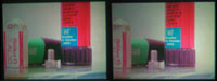
Figure 4. Projected left- and right-eye stereoscopic images are shown as seen through circular polarization-sensitive eyeglasses.
Meet the authors
Lawrence Bogaert, Youri Meuret and Hugo Thienpont are members of the department of applied physics and photonics at Vrije Universiteit Brussel, Belgium