Peter Domenicali and Stephen D. Fantone, Optikos Corp.
Microscope objectives represent an interesting case in the field of imaging performance metrology. In a parallel to mainstream photographic lenses, users of microscope objectives typically are more concerned with subjective performance – i.e., apparent image clarity and sharpness, or the ability to resolve a particular structure – than they are with objective measures of lens performance, such as the modulation transfer function (MTF).
Furthermore, given the typical visual usage of such lenses, deterioration of performance with field angle is generally acceptable. Users are accustomed to seeing images that are sharpest in the center and that degrade slightly toward the edges, and when eyepieces are used rather than a CCD camera, the user’s vision can generally accommodate for field curvature.
However, there are applications involving step-and-repeat surveying of large areas, including automated microscopy, fluorescence and whole-slide digitization, for which performance at the edge of each field is just as critical as that at the center. Mature production of complex systems, in which the microscope objective is just one component among many contributing to final system performance, typically benefits from statistical process control incorporating quantitative assessment of each significant subcomponent, enabling deterministic quality assurance and timely prediction of final system performance.
Techniques for measuring the MTF of a wide variety of lenses are well-known and MTF metrology architectures, such as the OpTest system by Optikos Corp., incorporating the VideoMTF system for image capture and data reduction,2 are available in mature embodiments for measuring the imaging performance of typical lenses having speeds faster than f/1.0. This corresponds to a numerical aperture, or NA, exceeding 0.5. Figure 1 shows an architecture such as this in schematic form.
Significant obstacles turn up
However, when measuring the MTF of high-NA microscope objectives, for example with an NA >0.70, we begin to run into two significant obstacles. First, the NA of the relay lens (consisting of the microscope objective and tube lens in Figure 1) must exceed that of the lens under test, to capture all of the transmitted light. Second, the MTF of the relay lens must be nearly diffraction-limited at the spatial frequencies of interest so that its contribution to the total measured MTF may be calibrated out. These requirements place heavy demands on the relay lens, as the NA of the lens under test goes up and its focal length goes down, factors that drive the region of interest toward higher spatial frequencies.
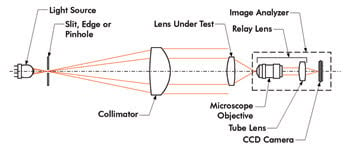
Figure 1. A typical MTF metrology system.
One may attempt to characterize the performance of microscope objectives interferometrically, but, unfortunately, monochromatic evaluation is insufficient to characterize the performance of most objectives, and field curvature evaluation with an interferometer is difficult. Even in relatively narrowband fluorescence systems, polychromatic measurement is essential to properly characterizing objective performance. Any residual axial color will reduce the on-axis MTF, and lateral color, which is difficult to characterize interferometrically, can dramatically reduce the off-axis MTF.
High-NA metrology architecture
Faced with an application to measure a state-of-the-art 60× oil-immersion microscope objective having an NA of 1.49, we realized that the architecture shown in Figure 1 would require the use of a second objective similar to the relay lens, leading to a recursive challenge in calibrating that relay lens. In response to this challenge, we developed the metrology architecture shown in Figure 2.
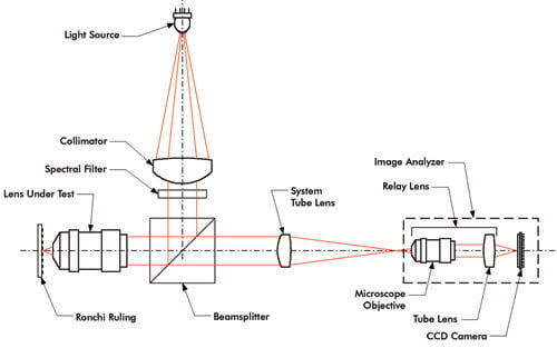
Figure 2. A high-NA MTF metrology system.
Rather than projecting a collimated image of a target structure “backward” through the lens under test, as would be done under the architecture of Figure 1, the new architecture employs a beamsplitter and implements epi-illumination to illuminate a suitable target structure placed at the object plane of the lens under test.
The chosen target structure is a reflective Ronchi ruling, consisting of chrome-on-glass lines and transparent spaces. Circular and radial lines and checkerboard patterns also can be used. The spatial frequency of the ruling was selected so that one line-space pair fills most of the field of view of the objective being tested. Importantly, the illumination source was designed to fill the rear pupil of the microscope objective, ensuring that the latter functions at its full design NA during this test. The spectral distribution of the illumination also can be chosen to match that of the intended application.
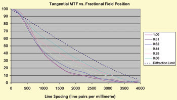
Figure 3. MTF plots versus fractional field position.
The objective under test was designed for use at infinite conjugates, as is the case for most modern microscope objectives. Therefore, the image it produces at infinity is re-imaged to a finite conjugate plane by the system tube lens, the same lens used for that purpose in the target system design.
Acquiring discriminatory information about the quality of the resulting image requires that it be sampled at a spatial frequency substantially higher than what could be obtained by a CCD imager placed at that image plane. Similar to the system shown in Figure 1, Figure 2 shows a low-power microscope objective employed as a relay lens, magnifying the image before projecting it onto the CCD sensor. The NA of the tube lens is rather low (~0.025, corresponding to f/20), allowing for a relatively slow relay lens to be used to magnify the image.
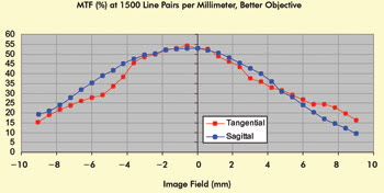
Figure 4. MTF results for a “better” example of a 60× 1.49-NA objective.
In use, a single dark-to-light transition from the Ronchi ruling is centered within the field of view of the CCD. The patented image processing algorithms within Optikos’ VideoMTF system use the edge-spread function to calculate the MTF. In its simplest form, this process consists of differentiation followed by taking the fast Fourier transform and applying system calibration information.
Because the Ronchi ruling – or alternative repetitive line/grid pattern – fills the lens under test’s field of view with multiple identical line edges, a motorized stage that traverses the image analyzer (which consists of the relay lens and the CCD) across the extent of the image at the back focal plane of the system tube lens enables acquisition of the MTF data as a function of field position.
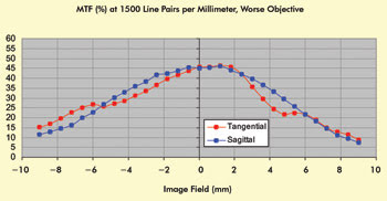
Figure 5. MTF results for a “worse” example of a 60× 1.49-NA objective.
At any given field position, the MTF can be expressed as a two-dimensional graph of MTF versus spatial frequency. By repeating this measurement over a range of field positions from the center to the edge, we obtained the plot in Figure 3 showing a family of MTF curves for a typical 60× objective: Note that the dashed line in this plot represents diffraction-limited resolution.
A subset of the data so obtained may be plotted as MTF at a chosen spatial frequency versus field position. Figures 4 and 5 show such plots for “better” and “worse” examples of the same model of microscope objective, for a chosen spatial frequency of 1500 line pairs per millimeter.
Figure 6 shows a plot of sagittal and tangential MTF for an objective that exhibits asymmetry in its performance across the field. Note that the peak MTF occurs at different field positions for the sagittal and tangential orientations.
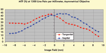
Figure 6. The MTF results for an asymmetrical example of a 60× 1.49-NA objective.
The overall strength of this approach is that the degradation of MTF from the diffraction-limited ideal is directly connected to the performance of the objective under test, and that the measurement does not rely on using an extremely high NA reference relay lens. We have found significant variations in MTF within batches of commercially sold microscope objectives and have obtained a real benefit – i.e., improved imaging results – when using objectives that are “cherry picked,” or prequalified, using this tool and its associated OpTest software. These “cherry picked” objectives also have been found to produce higher signal-to-noise ratio results in fluorescence measurement systems.
Meet the authors
Stephen D. Fantone, PhD, is the founder, chief executive officer and president of Optikos Corp. in Wakefield, Mass.; e-mail: [email protected]. Peter Domenicali is an engineering fellow at Optikos; e-mail: [email protected]
References
Carellas, P.T. and Fantone, S.D. (June 1990). “Why Measure MTF?” Optics and Photonic News, pp. 27-29.
U.S. Patent 5,661,816, Fantone et al, Image Analysis System.