Phil Alibrandi, Gigaphoton USA Inc.
As the lithography
capital equipment sector moves toward early field deployment of extreme-ultraviolet
(EUV) scanners and support, the 13.5-nm EUV energy source continues to be a key
factor in the ultimate adoption and economic success of the technology. Given the
high price of capital equipment investment, traditional high-volume manufacturing
(HVM) measures continue to be relevant and are hurdles to wide-scale acceptance
by chip makers.
In 2002, Gigaphoton began drawing upon the resources of Komatsu Ltd.
of Hiratsuka, Japan, and its ongoing work with the Extreme Ultraviolet Lithography
System Development Association in Tokyo. Early on in this collaboration, laser-produced
plasma (LPP) emerged as a preferred method of energy creation. Because of the technique’s
scalability, higher efficiency and the inherent spatial freedom of the plasma, the
CO2 laser-tin-LPP scheme is a promising candidate for long-term HVM success.
Specific features in development address three obstacles: productivity,
reliability and cost of ownership. They include – but are not limited to –
prepulse strategy, droplet generation, ease of maintenance/access, tin droplet debris
mitigation and collector mirror lifetime.
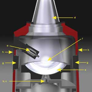
Figure 1. Illustration of an EUV chamber: (a) tin droplet generator, (b) prepulse laser port, (c) main laser port, (d) EUV output, (e) collector mirror, (f) plasma ball, (g) ion catcher and (h) superconducting magnets, located outside the chamber. Images courtesy of Gigaphoton USA Inc.
Conversion efficiency and prepulse strategy
In the semiconductor industry’s drive for initial 250-W
source power at the 13.5-nm wavelength for HVM, conversion efficiency is the metric
used to track energy from the CO2 laser to the EUV scanner. The beginning 5 percent
target is only one factor in the equation needed to reach economical production
throughput (power).
A conversion efficiency of 3.3 percent is achievable; the key
to reaching the 5 percent requirement is a YAG laser prepulse strategy. This is
an optimal wavelength for inducing thermal expansion of the tin droplet and for
creating a fine mist, exposing more material to the main CO2 laser pulse for maximum
in-band energy conversion.
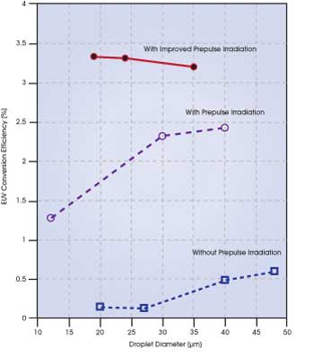
Figure 2. The graph shows a proof of concept for an optimized prepulse
strategy using two independent Gigaphoton Inc. lasers with different wavelengths.
In combination with an optimized droplet size, this prepulse,
distinct from the main power laser, allows for improved laser timing control and
100 percent tin ionization. It precludes premature energy loss. Only these conditions
create the proper reverse slope leading to the necessary conversion efficiency,
with no increase in droplet size or excessive tin debris. To reach ≥5 percent
conversion efficiency, a gating item for ≥50-W power, all entrants still have work
to do (see Figures 2 and 3).
Droplet generation
Tin droplet size, uniformity and Z-direction location also are
significant technical challenges to successful HVM operation.
Unique concepts in nozzle design and material purity in sub-20-µm
droplet extraction highlight the importance of cooperating closely with droplet
generator subsuppliers. The algorithms and control needed to acquire, track and
impact these targets at 100 kHz are nontrivial but well along in development and
execution.
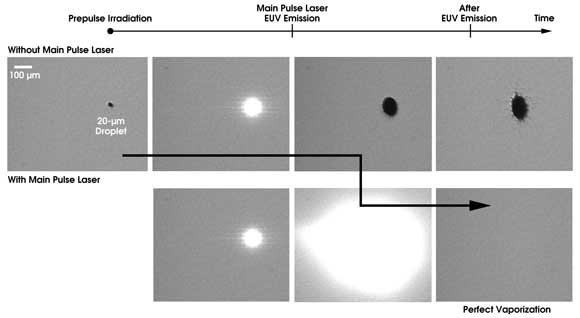
Figure 3. Shown over time are shadow graph images of the independent
prepulse strategy with resulting minimization of tin fragments. Note the thermal
expansion of the droplet, conserving potential energy prior to the main pulse.
Debris mitigation
The unavoidable result of tin ionization is debris created by
ions, neutrals and potential tin fragments. Without an effective strategy for avoiding
and eliminating debris, the collector mirror quickly becomes contaminated. Its effective
lifetime and availability are reduced, and the cost of ownership increases. As little
as 1 nm of deposition is estimated to reduce reflectivity by 10 percent, a likely
trigger for mirror replacement.
Proper droplet size and an independent prepulse can avoid fragments
and maximize ionization. Magnetic ion guiding, now a proven method, is used to mitigate
debris. In the EUV chamber’s vacuum environment, ionized tin atoms are guided
to the tin catcher by a magnetic field, created by placing superconducting magnets
on either side of the chamber (see Figure 4). The magnets are well integrated with
the source in terms of both size and safety.
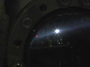
Figure 4. Tin ions, guided toward the tin catcher, are visible in
the magnetic flux, well above and parallel to the collector mirror.
To minimize the deposition of tin neutrals on the mirror, a chemical
cleaning process involving a common gas at low pressure is used. Sweeping away debris
magnetically, well away from the collector mirror, is not only a low-risk technique
but also permits a very small chamber design and a mirror diameter of just 400 mm.
There is no need for extra-large vessels or high gas flows to protect the collector
mirror, especially in this vacuum area. This type of EUV chamber need stand only
about 1.5 m – significantly smaller in dimension and volume than discharge-produced
plasma or other LPP designs.
Conclusion
Significant challenges are involved in designing, manufacturing
and supporting EUV technology to achieve an economically viable HVM lithography
solution per the International Technology Roadmap for Semiconductors, the industry’s
15-year assessment of its technology requirements. Ongoing EUV source development
and solutions in prepulse strategy, debris mitigation and chamber size will result
in various benefits to end users. These will include more efficient power and wafer
output, and higher reliability and uptime, with a resulting lower cost of ownership.
The industry requirement to reach 250 W of clean power at intermediate focus will
be realized by the extension of main CO2 laser power from current levels to 23 kW
and conversion efficiency from ~3 to 5 percent.
Meet the author
Phil Alibrandi is director of sales and international account
management for Gigaphoton USA Inc. in Beaverton, Ore.; e-mail: [email protected].
Reference and acknowledgment
H. Mizoguchi et al (April 2011). 100W 1st generation laser-produced
plasma light source system for HVM EUV lithography. Proc SPIE.
This work was partly supported by the New Energy and Industrial
Technology Development Organization in Japan.