Gregg E. Favalora, Optics for Hire
Clever use of electro-optics, lens arrays, diffusers and software advances the multidimensional way of seeing
The broad field of autostereoscopic display – the creation of imagery that appears three-dimensional without requiring the use of additional eyewear1,2 – is evolving. Optical engineers continue to push 3-D display technologies to match depictions in science fiction movies. It’s 2012, after all – can’t one simply buy a “holographic video display” that snaps into a DVI port and generates a cubic meter of full-color, occlusion-bearing, utterly natural imagery?
Well, almost.
There is much to consider in our journey, with 38 species of stereoscopic and autostereoscopic displays in 3D@Home’s taxonomy, and several possible classifications.3,4 (Reference 3 is a recommended starting point for technically oriented newcomers to the topic.)
The 3-D display is just one element of a broad pipeline spanning content generation, or acquisition, to the production of a 3-D image (Figure 1).
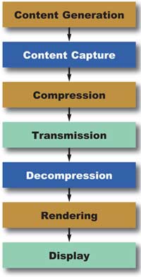
Figure 1. The data pipeline from scene capture to display. The “display” block may further include the steps of calibration, local storage, local processing, control systems and 3-D image projection.
What are the aims of current research?
This depends on the particular use of each type of display. A mobile device, such as Sharp’s directional parallax barrier backlighting in the Nintendo 3DS, permits a solitary user to view the display at less than arm’s length, from one constant viewing angle. Therefore, a two-view autostereoscopic image suffices. Contrast this with the aims of research in autostereoscopic television, which might require hundreds of unique viewpoints to numerous simultaneous viewers at various distances and viewing angles or, alternately, some combination of head-tracking and fewer unique views. Finally, consider boardroom and military uses, in which 10 people might encircle a horizontal display that projects volume-filling imagery above a tabletop.
Other than mobile, which I consider “solved enough” because of technologies from Sharp, MasterImage 3D and 3M, the field is experimenting with acceptable solutions for larger displays. Researchers still yearn to combine high-definition (HD) resolution, a natural effect of horizontal motion parallax for multiple simultaneous viewers, and the high-fidelity reproduction of depth both in and out of the display surface. For example, there are many vendors of flat panel autostereoscopic displays for desktop or living room use, but these devices usually are hampered by uncomfortably narrow restrictions on the viewer’s head placement within a viewing zone.
Bandwidth requirements
Most autostereo displays generate imagery by electro-optically modulating illumination; e.g., a display might sequentially direct photons modulated by a microelectromechanical system (MEMS) toward a series of viewing zones, or use a lens array to direct the light from many LCD pixels to several simultaneous zones. Their image quality is constrained by the modulator’s bandwidth, which is a function of time and space: the product of the number of light-modulating elements and the rate at which they can change state. Three-dimensional displays of comparable image quality consume more bandwidth than 2-D displays for a variety of reasons.
For example, some autostereo displays project a collection of perspective images, or views, in sequence to different angles in rapid sequence. Perceived depth increases with various factors, such as tighter angular definition of each of those views, which ends up consuming spatial bandwidth as the number of views increases.
Increasing the number of views is another desirable outcome because it decreases the distraction of interview aliasing, or flipping, in which one perceives the imagery jarringly change from one view to the next,5 but this consumes space or time bandwidth, too. Or, for a particularly elementary example, if the 3-D display uses an LCD panel, its resolution influences the system’s perceived resolution. Bandwidth, therefore, enables or constricts the optical engineer’s ability to provide image fidelity.
Let’s say you’re designing a display with numerous views to provide a comfortably wide viewing zone. Consider a 300-view, 1080-p autostereo display, with eight bits for each of three color channels, running at 60 Hz. This implies that you need the following light-modulation space bandwidth product (SBP):
SBP = 300 views x (1920 x 1080) pixels/view x 24 x 60 (s—1) = 895.8 billion pixels/second.
To my knowledge, Texas Instruments’ Digital Light Processing (DLP) technology offers the highest SBP in a rectangular array. For example, the ALP-4.1 made by ViALUX Messtechnik + Bildverarbeitung GmbH in Chemnitz, Germany, uses the Discovery 4000 chipset, providing 22,727 XGA-resolution fps at single bit depth, equaling nearly 18 billion pixels per second.
This is a tremendous improvement over other modulators, but still almost two orders of magnitude less than what is required for some types of displays. Thus, most experimental high-view-count 3-D displays have limited color fidelity, require multiple light modulators and provide significantly fewer than 300 views, which some researchers believe is desirable.
One method for improving image quality in the absence of sufficient SBP is the intentional blurring or band-limiting of elements of the displayed 3-D scene with increasing distance from the display, a technique developed by Michael W. Halle.6
Similar calculations hold for other display types. The Perspecta volumetric display stacked 198 2-D XGA-resolution slices of a scene with three-bit color at 30 Hz using a three-DLP light engine. Thus, a 100-million-pixel image was created at the expense of color fidelity.
Spatially multiplexed displays
Spatially multiplexed displays are those autostereo 3-D displays most frequently encountered by the public. Two examples are parallax barrier displays and lenticular displays. See the left panel of Figure 2, which illustrates an example of the former. Invented in the early 1900s, spatially multiplexed displays contain at least two views (one for each eye) interleaved on a surface, such as in vertical columns or other subpixel groupings. These are made selectively visible from several viewing locations or “sweet spots.”
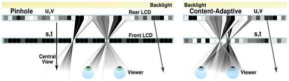
Figure 2. Cross-sectional views, looking down. Left: A traditional parallax barrier display places a regular array of transparent columns in front of an image source. In some displays, the role of “rear” and “front” LCDs are swapped. Right: A content-adaptive display computes optimized patterns on both display surfaces to improve the fidelity of the reconstructed scene. (Not to scale; the viewer is usually significantly farther away.) Courtesy of Matt Hirsch, MIT Media Laboratory.
Today, these displays typically offer between two and eight views, sometimes more, with 24 cited as an approximate practical upper limit because of the trade-off between view count and perceived resolution, and the impact of diffraction and light efficiency.
You might have seen a lenticular array used as a multiple-image panoramagram on DVD cover art or on advertising posters. In that case, a sheet of narrow lenslets directs an interleaved arrangement of views to a collection of zones in space – the word “panoramagram” implying that more than two views are created.3
Users of the Nintendo 3DS see two-view autostereoscopic imagery in a variation of the parallax barrier technique, directing illumination past microscopic columns of a rear LCD panel en route to an image-bearing front LCD panel. This is a rearrangement of the left illustration in Figure 2.
One of the many vendors of lenticular panoramagrams – and related software and services – is Paris-based Alioscopy. The company sells four lenticular displays, from 61 to 119 cm diagonally, each providing eight views. Firms differentiate the quality of their displays in various ways, such as custom lens design, careful quality control during manufacturing and registration, and proprietary algorithms.
Alioscopy reports that it fabricates lenses on-premises and applies them at an angle to the vertical axis of the underlying LCD display panel (Figure 3). This intentional slant is used in various lenticular displays to reduce moiré effects and to equalize perceived horizontal and vertical resolutions. The firm also is exploring plug-and-play systems, which combine hardware and software for a turnkey effect, such as a simulated 3-D aquarium that works out of the box.
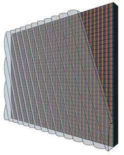
Figure 3. Some lenticular displays align the lens array on a slant with respect to an underlying interleaved image source. Courtesy of Alioscopy.
A third popular category of spatially multiplexed displays provides parallax not only in the left-to-right direction, but also in the up-down direction. These integral image displays use either fly’s-eye lens arrays or an array of tiny apertures, through which views can be seen. Integral imagery, also a 1900s invention, is seeing the most prolific ongoing development in Asia by companies such as NHK and Toshiba.
Professor Henry Fuchs and colleagues at the University of North Carolina at Chapel Hill have been developing a modern improvement of this technique, called random hole displays. In a recent version of the technique, a 2560 x 1600-pixel display is oriented horizontally, like a table, and viewed through a Poisson distribution of tiny apertures in a polyester film 6.35 mm above the display. In one mode of operation, two location-tracked simultaneous viewers each see approximately 2.8 million pixels that change with viewer motion.7
Time-multiplexed displays
Not all autostereoscopic displays use purely spatially multiplexed input imagery. The frame rate of certain light modulators is high enough to enable new display architectures to have time-varying properties, such as sequentially scanning the visibility of a series of 2-D patterns left and right across the audience, so that a multitude of unique perspectives can be depicted. These are time-multiplexed displays. The Discovery 4000 referenced earlier can depict about 378 binary patterns cycled at 60 Hz. An area of open research regards the mechanisms by which those patterns can be scanned.
One method, dual-lenticular scanning, was developed by Actuality Systems,8 and similar methods are being pursued by Zecotek Photonics Inc. of Richmond, British Columbia, Canada, and by the Brussels Photonics Team.9 In this method, a DLP-based projector directs a sequence of images toward a “sandwich” of two or more lenticular arrays that repeatedly translate left and right by a distance a fraction of the lenslet pitch; e.g., 125 µm. This forms a macroscopic beam-steering device.
Besting traditional spatially multiplexed lenticular displays, these temporally multiplexed displays can provide 100 or more viewpoints, each at XGA resolution. This results in imagery having a comfortably wide horizontal field of view for at least one user, providing excellent look-around and a compelling sensation of depth, though at the expense of color fidelity.
It also is possible to project 3-D imagery visible 360° around a flat horizontal surface. These theta-parallax-only (TPO) displays use a swiftly rotating disk-shaped optical component to repeatedly sweep a rapid sequence of viewpoints in a circle above the system.10 The purpose of the component is to restrict the active viewing angle at any given instant, and the projected image changes in synchronization so the appropriate image is directed to each viewing angle.
Absent viewer location compensation, the imagery has distortion when viewed from above or below the intended viewing height, but the results are promising. The optical component can take several forms: a disk cut out of an off-axis Fresnel lens, or a directional diffuser.
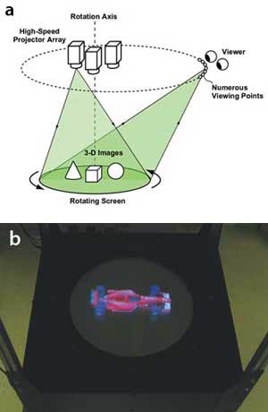
Figure 4. Each projector in a system made by the Takaki
Laboratories directs 800 images toward a rotating horizontal screen. The
result is a 360° display with a 300-mm diameter (b). Images courtesy of
Yasuhiro Takaki.
As shown in Figure 4, the Takaki Lab at Tokyo University of Agriculture and Technology produced a system incorporating several projectors illuminating a rotating disk.11 Other TPO displays include a commercially available display from Holymine Ltd. of Kanagawa, Japan; the “fVisiOn” system developed by the National Institute of Information and Communication Technology in Tokyo, which uses a cone-shaped directional diffuser; and the work of Xu Liu and his colleagues at Zhejiang University in Hangzhou, China.
Volumetric and multiprojector displays
Another type of 3-D display produces volume-filling imagery: volumetric displays, which offer many benefits.12 The eyes converge at the same point on which they focus, the imagery offers full parallax or “look around,” and the voxels that make up a 3-D image truly occupy a volume of space that looks correct to simultaneous users.
My former company, Actuality Systems, developed an approximately 100-million-voxel volumetric display, Perspecta, which illuminated a flat diffuse surface with 198 x 2 2-D patterns as it rotated about a vertical axis at 900 rpm.12 The technologies were acquired by Optics for Hire in 2009. Other examples include displays that ionize molecules in the air, creating groups of glowing addressable spots in 3-D13 and systems that rapidly move the intersection point of several infrared lasers within a medium doped with rare-earth ions.14
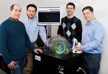
Figure 5. The Perspecta volumetric display created 100-million-voxel imagery from medical scans, 3-D graphics applications and seismic data. Pictured are M. Massey, M. Goldstein, J. Napoli and the author, with PerspectaRAD, an application for viewing and modifying external-beam radiation therapy plans. Photo by Sara Forrest.
How likely is it that tomorrow’s 3-D movies will be viewed without glasses, as they were in several periods in the last century?15 Holografika of Budapest, Hungary, has worked under the leadership of Tibor Balogh since the early 1990s to develop autostereo displays that scale to cinema sizes. A group of custom modular projectors illuminates a selectively diffuse screen, providing each audience member with a unique view of the imagery. Pictured in Figure 6 is the C80 cinema display, measuring 3 x 1.8 m, providing bright 1500-cd/m2, 24-bit RGB color imagery visible across a 40° horizontal field of view, using 80 projector modules.
At these densities, the eyes may see rays of light projected by more than one projector at a time. Therefore, the underlying software considers groups of independently addressable rays that intersect in groups at each point in the image – a subtle distinction over displays that are strictly “view”-based.
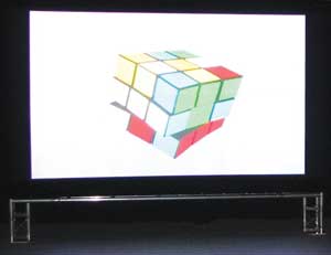
Figure 6. The HoloVizio C80 cinematic display. Courtesy of Holografika.
What’s next?
Nearly every aspect of 3-D system design – from capture to processing and displaying – is still a vibrant area of research. Among the hottest topics for 2012 are the benefits of tightly coupling the mathematics of optimization to the functions of pixels and barriers, some recent progress in electroholographic display and cross-disciplinary results from computational photography.
A successful recent example of computational displays is the work being done by MIT Media Laboratory’s Camera Culture Group in Cambridge, in which a stack of transmissive LCDs modulates illumination to provide 3-D imagery of greater expressiveness than the original parallax barrier displays of the 1900s.16
Traditionally, as described above, a regular array of vertical opaque-and-translucent columns directs left- and right-eye views toward just two viewing zones. In contrast, content-adaptive displays rely on the techniques of mathematical optimization to compute – dynamically – what patterns on the front, rear and any intervening surfaces best approximate a desired light field. This is illustrated in the right panel of Figure 2. The group’s analysis also extended the linear algebraic notion of rank to the world of display technology. A rapid sequence of various multilayer frames within the eye’s integration period results in 3-D imagery reconstructed with higher fidelity, increasing the system’s effective rank.
Others seek to provide more realistic curvature to the wavefronts emanating from 3-D displays in the hope of encouraging the eyes to converge and focus at the same place (unlike, for example, desktop stereoscopic displays in which your eyes focus at the screen regardless of the depth of a reconstructed point in a scene).17
Also, autostereoscopic display engineers continue to yearn for progress in applied physics to provide devices with greater numbers of rapidly modulating pixels. Imec in Louvain, Belgium, is developing MEMS technology with a pixel count that it hopes is sufficient for true holographic video display,18 while the Object-Based Media Group of the MIT Media Laboratory has been developing aspects of the pipeline shown in Figure 1, such as fundamental light-modulator components and methods of rapid 3-D scene capture for a future holographic 3-D display.19
Furthermore, cross-disciplinary work is being done within computer graphics, signal processing and optics. It is possible that the field of 3-D display technology will benefit from advances in light-field cameras, a topic described as early as 1908 with integral photography and rejuvenated by recent camera products from Lytro Inc. of Mountain View, Calif., and Raytrix GmbH of Kiel, Germany. Another result of cross-disciplinary work is the mathematical theory of light transport treated as manipulations in Fourier space, including the research of Frédo Durand and his colleagues at MIT.20
Advances are announced at global conferences, such as the SPIE-IS&T Stereoscopic Displays and Applications conference, a part of Electronic Imaging, each January in California. Topics include 3-D capture, compression, processing, display and perception, with vibrant work being reported across the spectrum.
Meet the author
Gregg E. Favalora is a principal at the engineering consultancy Optics for Hire in Arlington, Mass. He founded and was CTO of the autostereoscopic technology firm Actuality Systems; email: [email protected].
Acknowledgments
The author wishes to thank the following 3-D display pioneers for updates and materials: Matt Hirsch, Douglas Lanman, Pia Maffei, V. Michael Bove Jr., Yasuhiro Takaki, Papp Tamás and Zsuzsa Dobrányi. He also is grateful to Matthias Ferber and John Ellis for providing feedback on a draft of the manuscript. The author discloses that he is a chairman of the aforementioned SPIE-IS&T conference.
References
1. N.S. Holliman et al (June 2011). Three-dimensional displays: A review and applications analysis. IEEE Trans Broad, Vol. 57, Issue 2, pp. 362-371.
2. J. Hong et al (2001). Three-dimensional display technologies of recent interest: principles, status, and issues. Appl Opt 50, pp. H87-H115.
3. M. Halle (May 1997). Autostereoscopic displays and computer graphics. Comp Graph, Proc. ACM SIGGRAPH, Vol. 31, Issue 2, pp. 58-62.
4. S.A. Benton, ed. (2001). Selected papers on three-dimensional displays. SPIE, Vol. MS162.
5. T. Okoshi (1976). Three-Dimensional Imaging Techniques, Academic Press.
6. M.W. Halle (1994). Holographic stereograms as discrete imaging systems. Practical Holography VIII. Stephen A. Benton, ed. SPIE, Vol. 2176, pp. 73-84.
7. G. Ye et al (October 2010). A practical multi-viewer tabletop autostereoscopic display. Proc. ISMAR, Seoul, South Korea. IEEE, pp. 147-156.
8. O.S. Cossairt et al. Optical scanning assembly. US Patent No. 7,864,419. Provisional filed Jun. 8, 2004, issued Jan. 4, 2011.
9. L. Bogaert et al (2010). Demonstration of a multiview projection display using decentered microlens arrays, Opt Exp, Vol. 18, pp. 26092-26106.
10. G.E. Favalora and O.S. Cossairt. Theta-parallax-only (TPO) displays. US Patent No. 7,364,300. Provisional filed Jan. 12, 2004, issued April 29, 2008.
11. S. Uchida and Y. Takaki (2012). 360-degree, three-dimensional table-screen display using small array of high-speed projectors. Stereoscopic Displays and Applications XXIII, A.J. Woods et al, eds. Proc. SPIE-IS&T Elect Imag, Vol. 8288, 8288 0D.
12. G.E. Favalora (2009). Progress in volumetric displays and their applications. Front Opt, OSA Technical Digest (CD), paper FTuT2.
13. H. Saito et al (2008). Laser-plasma scanning 3D display for putting digital contents in free space. SPIE Stereoscopic Displays and Applications XIX. A.J. Woods et al, eds. Proc. SPIE-IS&T Electr Imag, Vol. 6803, p. 680309.
14. H.H. Refai (2009). Static volumetric three-dimensional display. Journ Disp Tech, Vol. 10, pp. 391-397.
15. W. Funk (2012). History of autostereoscopic cinema. Proc. SPIE-IS&T Electronic Imaging, Stereoscopic Displays and Applications XXIII. A.J. Woods et al, eds. Vol. 8288, p. 8288 0R.
16. D. Lanman et al (2010). Content-adaptive parallax barriers: Optimizing dual-layer 3D displays using low-rank light field factorization. Proc. SIGGRAPH Asia, ACM Transactions on Graphics. ACM Press, Vol. 29, Issue 6, pp. 163:1-163:10.
17. W. Plesniak et al (Nov. 29, 2006). Reconfigurable image projection holograms. Opt Eng, Vol. 45, p. 115801.
18. R. Courtland. Spring-loaded pixels to drive holographic displays. Weblog entry. IEEE Spect Tech Talk. Retrieved March 27, 2012, from http://spectrum.ieee.org/tech-talk/semiconductors/devices/spring-loaded-pixels-to-drive-holographic-displays.
19. V.M. Bove Jr. (2011). Live holographic TV: From misconceptions to engineering. Proc. 2011 SMPTE, International Conference on Stereoscopic 3D for Media and Entertainment.
20. F. Durand et al (2005). A frequency analysis of light transport. Proc. SIGGRAPH, ACM Transactions on Graphics, ACM Press, pp. 1115-1126.