David Jackson, Cleanlogix LLC
Advanced CO2 composite spray cleaning is an efficient and adaptable process for build-clean and maintain-clean protocols.
A common aspect of photonic devices is the presence of critical components that emit, transmit, modulate, amplify, divide, switch or otherwise process light over the whole spectrum from ultraviolet over the visible to the near-, mid- and far-infrared. Particles and residues absorb, attenuate or obscure light.
Because of this, critical light-processing elements of photonic devices must be free of surface particles and residues to properly function. These devices require effective (and sometimes very selective) surface cleaning and treatment during various stages of fabrication and testing – for example, during assembly; following polishing, soldering or wire bonding; or in preparation for the application of thin-film coatings or for adhesive bonding. Moreover, functional photonic devices such as fiber optic connectors and lenses require critical cleaning as part of a preventive maintenance program to ensure continued reliable performance.
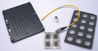
Figure 1. Photonic devices and substrates cleaned with CO2. The method can be used on a variety of optical components and instruments.
For example, specialized thin-film optical coatings often are required for optics that handle high-power output from lasers. The coating is typically the limiting factor in the output of a high-power laser system. The most common failure mode of high-power laser coatings results from the presence of absorption sites – typically, small particles and thin film occlusions – within the coating or at the coating’s interface with the substrate or air.1
But cleaning photonic devices presents challenges; e.g., contacting the surface directly with wipers can smear contaminants or scratch critical optical surfaces such as coatings and substrates. And component compatibility problems, drying and spotting challenges may be present. Many complex photonic devices can’t be completely immersed or sprayed with aqueous cleaners or solvents; in such cases, contact cleaning using soft brushes, solvent-wetted wipers or swabs must be used, which can introduce the risk of smearing or scratching critical surfaces, coating damage, and contaminant smearing or re-deposition – or not cleaning at all. So-called noncontact dry cleaning techniques such as canned air blow-off and solvent aerosol sprays may be used, but may not do the job properly or selectively enough.
Conventional carbon dioxide (CO2) aerosol spray cleaning (aka “snow cleaning”) is a noncontact technique that can be used by both photonic device manufacturers and end users. CO2 is safer and more effective than traditional cleaning procedures because it is noncorrosive and nontoxic, and it provides soft, scouring impingement particles and CFC-like solvent chemistry.
However, CO2 snow cleaning requires controlled, moisture-free mini environments to prevent atmospheric condensation and particle-residue redeposition on surfaces.2 Inert-atmosphere mini environments are expensive, constrain production flow, and limit in-tool and in-field photonic device cleaning applications as well as open-air cleanroom manufacturing operations. Although controlled work environments solve some of the challenges of optical cleaning and contamination control using conventional CO2 cleaning, the use of controlled environments and protocols can be both inadequate and constraining. Assembly operations often negate the benefits provided by cleanrooms. Clean assembly or build-clean protocols offer optimal optical cleaning and contamination control.3
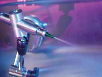
Figure 2. CO2 spray with a Coaxial composite spray nozzle.
Newer and more advanced CO2 cleaning and contamination technology enables the use of the highly flexible and adaptable build-clean and maintain-clean protocols on the bench, in the tool or on the production line.
CO2 composite spray cleaning
Advanced CO2 composite spray cleaning was developed in the late 1990s to address the drawbacks and limitations of conventional CO2 snow spray cleaning.4-5 A CO2 composite spray combines liquid CO2, a unique crystallization process, heated and ionized clean dry air, and Coaxial or Coanda composite spray nozzles to deliver a precisely controlled multiphase CO2 cleaning spray. CO2 composite spray cleaning provides several process control and performance advantages, including enhanced spray composition control, spray impact energy control and adaptability to existing manufacturing processes, tools and production lines.
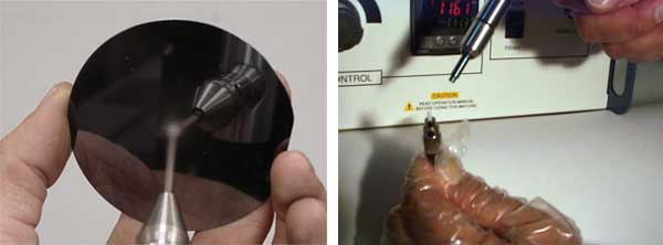
Figure 3. Cleaning a fiber optic connector.
CO2 consumption is reduced significantly while spray cleaning control and performance are greatly improved over conventional CO2 snow cleaning. The physicochemical cleaning principles involved in CO2 composite spray cleaning are analogous to microabrasive cleaning, with significant distinctions. One is the low hardness of CO2 particles (<1 Mohs). CO2 composite spray cleaning using (size-adjustable) microscopic particles of CO2 is a nonabrasive process. Another distinction is that CO2 composite spray cleaning processes involve physical momentum transfer and phase change phenomenon, and liquid CO2 solvent spray cleaning mechanisms to remove particulate and thin-film contamination from electro-optical surfaces.
For example, CO2 exhibits a solvent chemistry similar to halogenated cleaning solvents, which enhances the surface cleaning effect. Moreover, surface impact stress (microscopic particle cleaning energy) can be controlled precisely from less than 100 kPa to as high as 60 MPa.
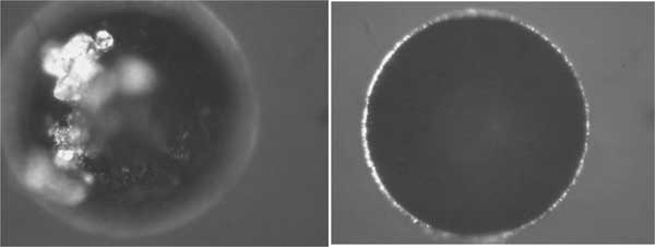
Figure 4. Postpolish cleaning results for a fiber optic surface.
CO2 spray-cleaning principles
The cleaning energy required to remove microscopic particles and thin films rises exponentially as the diameter of the particle or thickness of the film decreases; for example, increasing to several million g forces for submicron particles.6 Fluid velocities rapidly decrease from turbulent flow (high energy) to laminar flow (low energy) at microscopic distances from the surface. This is where the small particles and thin films “hide out.” To overcome this energy barrier, commonly known as “the wall” or the “boundary layer,” high fluid velocities must be achieved to increase fluid flow characteristics from laminar to turbulent, which increases viscous drag (also known as shear stress) upon the particle.
CO2 composite cleaning sprays are different from and superior to conventional high-pressure spray cleaning using liquid solvents or blow-off gases in two important ways: a unique chemistry that provides physical scouring action plus Freon-like solvency and the capacity to directly affect a substrate surface, completely overcoming the energy barrier.
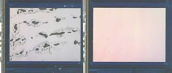
Figure 5. Cleaning a CMOS image sensor.
Clean-assembly protocol
Particles and other manufacturing residues accumulate on both support equipment and critical surfaces of photonic assemblies during manufacturing processes. An example of typical manufacturing contamination during the fabrication of CMOS image sensors is shown in Figure 6. Such contamination must be removed to prevent yield loss. Jigs, fixtures, transfer devices, carrier frames and trays (“support equipment”) must be cleaned prior to use inside a cleanroom environment and during use are a source of particle accumulation and transfer to photonic assemblies. As discussed earlier, photonic devices accumulate particles during manufacturing steps; best practices require precision cleaning at various stages of production to control particle burden – the “build clean” or clean assembly protocol.
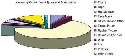
Figure 6. Examples of contamination distribution found in CMOS fabrication.
Careful consideration must be given to the many cleaning and inspection operations within the process flow for photonic device manufacturing. Cleaning frequency and methodology for support equipment and photonic assemblies in the cleanroom must be optimized. For example, if automated part transfer systems (i.e., vacuum picks) are not regularly cleaned, they can be a source of particles and other types of contamination. Particles and residues generated during assembly and test processes accumulate on the support equipment in the form of particle burden, which can transfer to subassemblies during handling. With the increasingly geometric complexity of the photonic subassembly during the manufacturing process, particle contamination becomes more challenging and time-consuming to remove.
Offline precision cleaning using spray or immersion cleaning processes is a common approach. However, this method can be labor-intensive and cause line stoppages in high-capacity manufacturing. Cleaning of complex support equipment can require multiple operations such as disassembly, removal from the cleanroom, precision cleaning, return to the cleanroom, reassembly and calibration. Likewise, photonic subassemblies requiring cleaning during build are often batched, precision-cleaned, dried and returned to the manufacturing line. All of these procedures are disruptive to product flow.
If process flow conditions related to particle and residue cleaning can be improved – proved by higher-assembly yield – then some cleaning and inspection steps can be eliminated or reduced, thus lowering the overall cost of photonic device manufacturing. CO2 composite cleaning sprays can improve particle cleanliness for support equipment as well as for spot cleaning photonic devices during build to reduce particle burden.
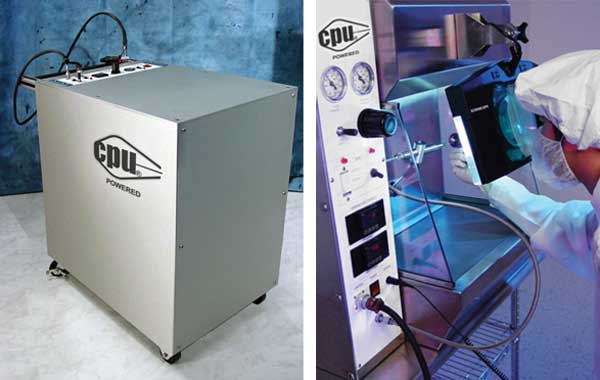
Figure 7. CO2 cleaning tools can be mobile (left) or installed at the benchtop (right).
CO2 spray cleaning tools are shown in Figure 7. These systems, with a local exhaust system, can be conveniently located on existing workstations throughout the cleanroom manufacturing line, as ionized air blow-off guns are, to facilitate photonic subassembly precision cleaning during build. Besides workstation solutions, a mobile cleaning system equipped with a tabletop work surface and HEPA-filter exhaust system can provide in situ cleaning of contaminated support equipment elements without complete disassembly. CO2 composite spray cleaning systems and methods easily adapt to new and existing manufacturing and assembly lines, production equipment and processes.
Meet the author
David Jackson is president of CleanLogix LLC, based in Santa Clarita, Calif.; email: [email protected].
References
1. I. MacMillan (May 2002). Creating high-power optical coatings is complex. Laser Focus World, p. 137.
2. E. Kubacki (March 2006). The dirt on cleaning optics. Photonics Spectra, pp. 56-60.
3. J. Pryatel et al (Jan. 5, 2006). Clean assembly practices to prevent contamination and damage to optics. UCRL Conference 217973, Boulder Damage Symposium.
4. D. Jackson et al (May 1999). Using solid-state CO2 in critical cleaning, precision cleaning. Process Cleaning, Vol. VIII, No. 5, pp. 16-19.
5. D. Jackson (March/April 2007). Effective alternatives to traditional spray and immersion cleaning processes. Process Cleaning. http://www.processcleaning.com/articles/effective-alternatives-to-traditional-spray-and-immersion-cleaning-processes.
6. R.P. Musselman et al (January/February 1987). Shear stress cleaning for surface departiculation. J Env Sci, p. 51.
Cleaning applications
CO2 composite spray cleaning is a robust surface treatment platform for challenging substrates having complex or microscopic geometries. Many types of photonic devices can be precision-cleaned to address contamination challenges including particulate matter; oxides; and organic, outgasing and ionic residues. The technology also is being used to address process heat contamination during machining, thermal coating and other problematic heat-generating manufacturing processes.
Many hybrid processes combining CO2 composite spray and manufacturing processes are possible. The inherent synergies generated between CO2 and manufacturing technologies create numerous and creative manufacturing opportunities and benefits such as new production techniques and tools, compression of space, reductions in labor and energy, and decreased production time.
CO2 may be used in a variety of photonic device manufacturing and assembly processes. Examples include:
• Adhesive bonding
• Functional coating
• Encapsulation/sealing
• Wire bonding
• Welding
• Polishing
• Precision assembly (and test)
• Micromachining