John Filhaber, Zygo Corp.
A look at the geometric parameters of aspheres and how they differ from those of spherical optics as well as the metrology techniques required to quantify those parameters in manufacturing
Driven by the ever-increasing resolution and field size of focal plane arrays as well as the need for smaller, lighter-weight systems and lower manufacturing costs, aspheric lens elements are now ubiquitous in nearly every market from aerospace to consumer electronics. For years, manufacturing advances have focused on techniques and tools to improve surface figures, but many designers and system integrators now understand that the relationship between front-side and back-side geometries can be just as important, especially in controlling off-axis aberrations.
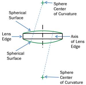
Figure 1. Feature types in a spherical lens.
Geometry of a spherical lens
The axis of a spherical lens is defined by the line that includes the centers of both surfaces. The edge of the lens is typically a cylinder, and its axis is its center line. Waviness, roughness and irregularity in the finished edge contribute to the tolerance of any dimension that uses the lens edge as a datum. In practice, the edge may be so thin that the direction of its axis cannot be located accurately, but its center can still be located and represented by a point at the center of the diameter (Figure 1).
If the axis of a spherical lens does not go through the center of the edge of the lens, the error is called wedge and is described as TIR (total indicator reading). This is commonly measured on a test station with an air bearing and a sensitive indicator. With the lens edge centered in the holder, the difference in thickness from one side of the lens to the other is measured at the clear aperture. This is the TIR or wedge (Figure 2).
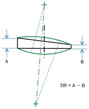
Figure 2. Wedge or total indicator reading (TIR) in a lens.
A spherical lens with no wedge may be aligned by minimizing the tilt of the surface it sits on and centering the edge of the lens relative to the optical system, as in Figure 3. A lens with wedge may still be aligned without error in a system, as the centers of curvature of the two surfaces can be placed on the axis of the optical system. A wedged lens thus aligned will exhibit a radial runout of its border or edge, but no change in thickness at any distance from the axis; therefore, no error is added to the wavefront. Figure 4 shows a spherical lens with wedge and its resulting placement in a system and wavefront. The lens will function perfectly, although the edges will not be perfectly centered.
Geometry of an aspheric lens
Figure 5 shows the three feature types that define the geometry of an aspheric lens: the edge of the lens, the optical axis of the aspheric surface(s) and the center of curvature of the spherical surface, if it has one.
The definition of the optical axis of a fabricated surface – particularly an aspheric surface – must be used consistently in the design, tolerancing and fabrication stages of lens production. For an aspheric surface with rotational symmetry, a common way to define the axis is to use an optimization routine to “move” the equation of the ideal surface over the data with tip, tilt, decenter and piston as free parameters, minimizing the root mean sum of the squares of the difference. The center of curvature of the sphere is simply the point that lies equidistant from every point on the surface of the sphere. In a perfect lens, all of these features line up exactly on a single line.
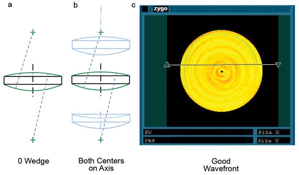
Figure 3. Spherical lens with no wedge (a) aligned in a system (b); (c) shows the resulting wavefront.
The system performance impact of a lens with a misaligned asphere will be a function of many factors, including the equation of the surface, the location of the surface in the optical system, the magnitude of misalignment and the contribution from figure error. Controlling the impact of this error begins in the tolerance-optimization phase of design. For optimization to proceed properly, all additional degrees of freedom for the geometry of single- or double-asphere lenses must be represented in a model that also includes assembly compensators if one expects the system cost to remain reasonable.
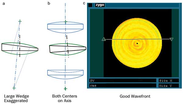
Figure 4. Spherical lens with wedge (a) aligned in a system (b); (c) shows the resulting wavefront.
Balancing aspheric lens manufacturing tolerances with the use of system compensators is arguably one of the most difficult aspects when designing aspheres into high-performance systems. The reason is that driving too tight a tolerance into the asphere will increase costs very quickly – but, without advanced assembly and metrology techniques, assembly compensators will become ineffective.
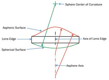
Figure 5. Feature types of an aspheric lens.
Specifying asphere geometry
Designers need to become very familiar with the capabilities of manufacturers and, in many cases, leverage the manufacturer’s internal design capabilities to properly manage tolerancing trade-offs. Design, manufacturing and metrology all prove to be a challenge, and very few companies excel in all areas. One of the most powerful DFM (design for manufacturing) tools for manufacturing is the telephone: Call your preferred vendor early in the design phase, and build your tolerance budget and assembly plan around demonstrated capabilities. The cost, schedule and risk benefits are dramatic.
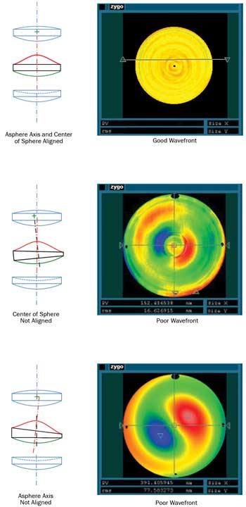
Figure 6. The impact of aligning various geometry errors in a simple optical system.
A poorly toleranced lens may not be able to be aligned in a system even if its surface quality and TIR are excellent. The goal of aligning aspheric lenses into a lens system is to place the axis of the aspheric surface, as well as the center of curvature of the second surface, on the axis of the system. This cannot be achieved if the center of curvature or the optical axis of the second surface does not lie on the first. An attempt to center the lens will invariably be a compromise between decentering and tilting one or both surfaces to achieve best performance. Figure 6 shows the impact of aligning various types of geometry errors in a simple optical system.
A wedge specification alone is not sufficient to control geometry errors in a lens with one or more aspheric surfaces. Figure 7 shows some combinations of in-and-out specification tolerances that do not always give expected results. It is possible for an aspheric lens to have minimal TIR and still have significant decenter of the optical axis relative to the edge of the lens. In detail, the decentered asphere will impart some waviness to the TIR around the edge in this case, but it will often be much smaller than the tolerance and difficult to interpret.
The critical relationship to be controlled is the distance between the sphere’s center of curvature and the optical axis of the asphere. Often it is convenient to specifiy the decenter of the asphere relative to the edge of the lens and also specify the TIR, as shown in Figure 8. A specification based on these two values might read: “Vertex of asphere <6 μm from center of the lens generated edge. TIR < 10 μm.” It is clear that the roundness and smoothness of the edge will contribute to the error inherent in this datum and should be verified. In practice, a carefully generated edge might contribute only a few microns to the error budget, but a specification of roundness and roughness of the edge is warranted nonetheless.
Measuring front-to-back asphere geometry
A distinction must be made between QA (quality assurance) metrology – metrology during processing and qualifying a lens – and alignment metrology. For final quality assurance of a lens element, a full surface measurement provides the best results and gives data that can be analyzed in many ways. In system assembly and alignment, simpler and more conventional methods can be used if the final quality assurance data of the lens is known to be good.
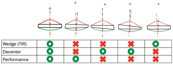
Figure 7. Some combinations of geometry errors in aspheric lenses.
Measuring the front-side-to-back-side relationship of an aspheric lens is the key to manufacturing a good lens. A simple way to do this on an asphere/sphere lens is as follows: The part under test is placed in a custom mount with the spherical surface resting on three precision contacts and the edge placed in contact with two precision balls. The lens is now constrained in five degrees of freedom, with rotation around the axis unconstrained. A full surface measurement of the aspheric surface is made using an interferometer system, a computer-generated hologram, a high-precision profilometer or another system. The optical axis will be reported in the coordinate system of the measurement tool.
It is important to note that locating the axis of an asphere by measuring two zones in a TIR-type measurement can result in an axis defined by a tilted or comatic zone. A full-area measurement does a better job of predicting global system performance. The part is then rotated 180° against the stationary part holder and measured again. As the part rotates, the axis of the asphere will orbit the center of its lens, defined by the precision balls in contact with the lens edge. Half the length of the line between the two reported centers is the distance from the center of the lens edge to the optical axis of the asphere.
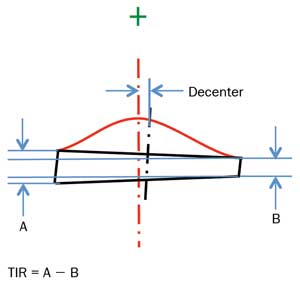
Figure 8. Decenter and TIR in an aspheric lens.
Figure 9 shows the results of eight centering measurements made with Zygo’s VeriFire Asphere on an asphere with a 60-mm diameter and a 500-μm departure from the base sphere. The data shows a 17.7-μm decenter (± 1 μm 1 σ). The origin is the mean center of the lens, defined by the contact between the lens edge and two precision spheres spaced 120 degrees apart.
The last remaining step is to measure the TIR of the lens using conventional methods. In this case, the TIR of the lens was in spec, so computer-controlled polishing was used to move the optical axis to within the 10-μm decenter specification in a single iteration.
In this example, having capable metrology and measurement techniques provided the fabricator with minimized production costs through one polishing iteration and ensured on-time delivery. By specifying parameters correctly, the designer ends up with a component with predictable performance. By combining traditional TIR techniques with full-surface aspheric metrology tools, important front-side-to-back-side parameters in aspheric optics become controllable – and final assemblies behave as desired.
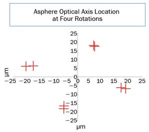
Figure 9. The results of eight centering measurements made with Zygo’s VeriFire Asphere on a 60-mm-diameter asphere with a 500-μm departure from the base sphere. The data shows a 17.7-μm decenter (+/- 1 μm 1 σ). The origin is the mean center of the lens defined by the contact between the lens edge and two precision spheres spaced 60 degrees apart.
Meet the author
John Filhaber is the director of special programs at Zygo Corp. in Middlefield, Conn.; email: [email protected].