3D imaging and ultrahigh resolution are ideal for the inspection of materials with defined surface finishes and textures.
ROBERT BELLINGER, Evident
When evaluating the surface of a component, surface roughness can be assessed by eye or by rubbing it with a fingertip. Common expressions include “shiny,” “lusterless and rough,” “like oxidized silver,” or “like a mirror.” The differences indicated by these terms are caused by the variations in the irregularities of the component’s surface.
The level of shininess — or asperity — of a surface is an important characteristic and can be quantified. Surface irregularities may be intentionally created by machining, but they can also be created by factors such as tool wobbling caused by motor vibration during machining, the quality of a tool edge, or the nature of a machined material.
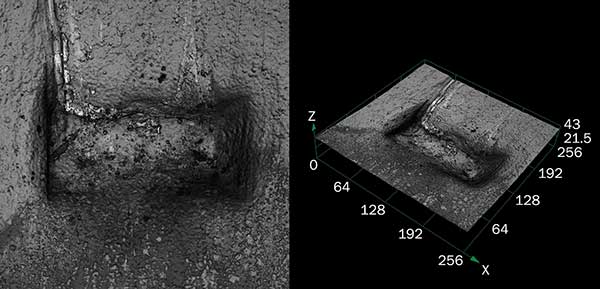
Figure 1. 2D image (left) and 3D image (right) of printed circuit board connector created using a laser confocal microscope.
The form and size of irregularities vary, and they are superimposed in multiple layers. Differences in these irregularities impact the quality and function of the surface.
Irregularities affect the performance of the end product in aspects such as friction, durability, operating noise, energy consumption, and airtightness.
Reasons for measuring surface roughness
The shape and size of irregularities on a machined surface have a major impact on the quality and performance of the surface. The quantification and management of fine surface irregularities are necessary to maintain high product performance.
Quantifying surface irregularities means assessing them by height, depth, and interval. They are then analyzed by a predetermined method and calculated per industrial quantities standards. The form and size of surface irregularities and the way the finished product will be used are what determine if the surface roughness acts in a favorable or an unfavorable way. For example, surfaces that will be painted should be easy for paint to adhere to, and drive surfaces should rotate easily and resist wear. It is important to manage surface roughness so that it is suitable for the component in terms of quality and performance.
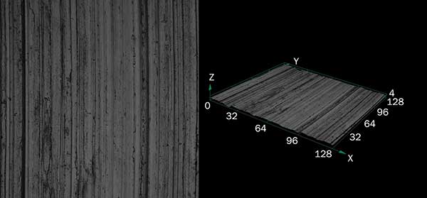
Figure 2. 2D image (left) and 3D image (right) of polished metal surface created using a laser confocal microscope.
Many parameters have been established regarding the measurement and assessment of surface roughness. As machining technologies progress and higher-quality products are required, the performance of digital instruments, especially laser confocal microscopes, continues to improve. The surface roughness of more diverse surfaces, including painted plastics, metal mating surfaces, solar panels, and circuit boards, can now be assessed.
Two measuring methodologies
Surface roughness measurement methods include linear roughness measurement (profile method type), which measures roughness on a single line of the sample surface, and areal roughness measurement (areal method type), which measures roughness over an acquired area of the surface. Linear roughness measurement had been the industry standard for many years, but expectations for areal roughness measurement, which gathers a larger surface sampling area, have risen in recent years due to advances in laser confocal microscopy.
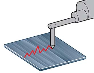
Figure 3. Linear roughness measurement performed with a contact stylus.
With linear roughness measurement (profile method type), the degree of roughness in the surface is measured along an arbitrary straight line. Long, continuous dimensions are measured, and a contact stylus is commonly used to perform the roughness measurement. Linear roughness measurement is compliant with ISO and other national standards.
Laser scanning for areal roughness measurements
With areal roughness measurements (areal method type), the degree of roughness in the surface is measured over an arbitrary rectangular range. Areal roughness measurement uses a larger sampling area of the surface, providing a more accurate depiction of the state of the surface. A laser scanner is commonly used to perform areal roughness measurement.
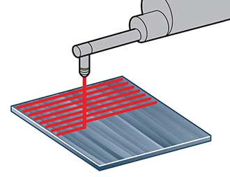
Figure 4. Areal roughness measurement performed with a laser scanner.
Contact and noncontact measuring instruments
The instruments used for measuring surface roughness can be broadly divided into two types: contact and noncontact.
With the contact type, the tip of a stylus directly touches the surface of the sample (Figure 3). As the stylus traces across the sample, it rises and falls together with the roughness on the sample surface. This movement in the stylus is picked up and used to measure surface roughness. The stylus moves closely with the sample surface, so data is highly reliable.
The leading noncontact method involves light. Light emitted from an instrument such as a laser confocal microscope, focus detection system, or interferometer is reflected and read, measuring without touching the sample (Figure 4). As they are noncontact, these systems do not harm the sample and can even measure soft or viscous materials.
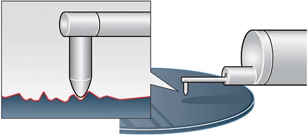
Figure 5. Contact-type roughness instrument.
Noncontact observations in 3D
With laser confocal microscopy, noncontact 3D observations and measurements of surface features at submicron resolutions are easy to produce. Measurements of this nature are extremely important when analyzing and testing the surfaces of mating metals, especially within the areas of aerospace, satellite design, automobile production, and military equipment production.
For example, if an engine component is going to be routinely subject to high RPMs, surface analysis at extremely
high resolutions is imperative to ensure safety, reliability, and performance. Additional benefits of laser confocal microscopy include fast image acquisition and high-resolution microscope images over a wide area, which can help save valuable testing and production time.
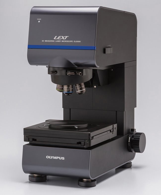
Figure 6. Laser confocal microscope (focus detection system).
The tip radius of a general contact-type stylus is about 2 to 10 μm, which causes the roughness data to be “filtered” by the size of the stylus. In contrast, the radius of a laser spot from a laser confocal microscope is only 0.2 μm, so it can measure surface roughness that a contact-type stylus cannot enter (Figure 5).
High accuracy of laser confocal microscopes
With a contact-type instrument, it is difficult to measure narrow areas such as fine wires (Figure 7). With a laser confocal microscope, however, positioning can be determined accurately, and it is easy to perform areal roughness measurement for a small target area (Figure 8).
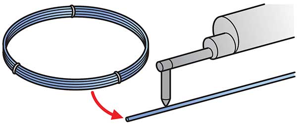
Figure 7. It is extraordinarily difficult to lower a stylus onto a wire surface only tens of microns across.
The use of laser confocal microscopes for measurement is largely divided into two categories: horizontal measurement using an intensity image at a high resolution and 3D measurement using a height image.
During horizontal measurement using an intensity image, the most important determining factor of measurement accuracy is control of the oscillation angle of the scanning mechanism. Many of today’s newest laser confocal microscopes are
periodically calibrated using a standard sample to ensure stable measurement for long periods of time. (The galvanometer mirror often used in the scan optical system uses a coil for position detection, so it takes some time to stabilize.) As the intensity dramatically changes around the focal position in the confocal optical system, focusing is one of the factors that affects the repeatability of a measurement result. When determining the line width of a pattern on a separated sample surface with a laser confocal microscope, it is desirable to use the relatively faster X-axis direction, which is not easily affected by vibration and other disturbances for measurement (especially because the X and Y axes have different speeds). A microelectromechanical systems (MEMS) mirror is used in the X direction to improve speed and accuracy.
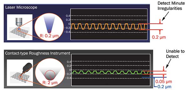
Figure 8. Laser confocal microscope vs. contact-type roughness instrument.
Measuring in three dimensions
The driving factor for accuracy in 3D measurement is the Z-drive mechanism, which can move the objective lens and sample relative to each other. The method of driving the revolving nosepiece to which the objective lens is attached in the Z direction or the method of driving the XY stage on which the sample is positioned in the Z direction are the possible implementations of a Z-drive mechanism.
If a laser confocal microscope is used to measure the height of a sample, the highest intensity at each pixel must be found by moving in the Z direction. Therefore, the travel mechanism must be accurately moved with a resolution of about
10 nm at the highest magnification. A highly accurate linear guide and feeding screw are used together, and a pulse
motor or other device is used in most cases to drive in increments of a few millimeters, usually with a resolution accuracy
of a few nanometers. A confocal optical system and a highly accurate Z-axis driving mechanism allow a laser confocal microscope to be used with the highest magnification objective lens and to resolve data down to several nanometers in the
Z direction.
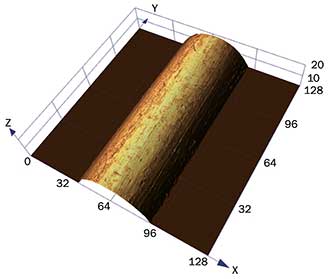
Figure 9. Observation image from a laser confocal microscope. Extremely fine wire (φ50 µm), objective lens magnification 100×.
Dental implants all roughed up
3D surface measurement using a height image is critical within a number of industries, including the manufacture of medical implants and devices. In the case of dental implants, the surface roughness of the root portion of the implant is important because roughness increases the overall surface area which, in turn, increases the implant’s stability. The metal portions of dental implants often undergo multiple processing stages to increase roughness including blasting, acid etching, anodic oxidation, and polishing. The optimum surface roughness for dental implants is between 1 and 10 μm. In Japan, dental implant manufacturers are required to verify the measurements of surface roughness using a laser confocal microscope. Failure to have appropriate roughness can lead to poor adhesion of an implant to a patient’s mouth.
Many of the newer advanced laser confocal microscopes offer high levels of accuracy and precision in measuring the roughness of dental implant surfaces. One model, for instance, can measure steep angles so that shapes of varying geometry can be accurately and precisely measured (Figure 10). Utilizing a long working distance objective lens, the microscope allows more separation between the sample surface and the microscope lens so that larger objects, such as dental implants, can be accurately inspected.
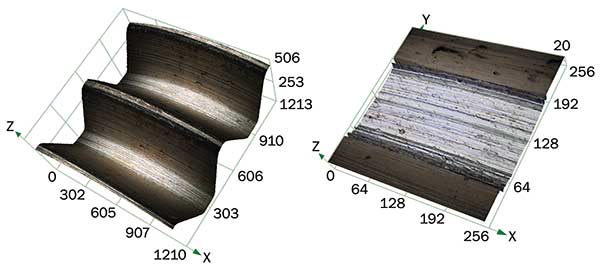
Figure 10. Dental implant surface measurements.
Conclusion
Additionally, the latest laser confocal microscopes deliver the ability to make 3D observations with ultrahigh-resolution measurements and a high pixel density. Varying objectives give the user the flexibility of having a working distance capable of accommodating larger objects. High inclination sensitivity provides the ability to make accurate measurements of complex and steep-sided irregularities.
Widely used in quality control, research, and development across an array of industries and applications, laser confocal microscopes have set new standards in 3D surface roughness measurement. As demand grows for increased measurement precision and wider observation applicability, these instruments have continued to evolve to facilitate faster, easier measurement and higher-quality imaging. Benefits include fast noncontact, nondestructive measurement; accurate measurement of submicron distances across the XY axes; superior Z-axis measurement; wide sample ranges; high-angle measurement capabilities; performance guarantees; a wide range of measurement types; realistic surface reproduction; and crystal-clear 3D images.
Author Robert Bellinger is the Product Applications Manager, Industrial Microscopy at Evident.