Long-used in the telecommunications industry, fiber Bragg gratings are now used to measure the strain and temperature of buildings, roads and bridges. A new technique involving collimators and a series of the fiber Bragg gratings can monitor strain in rapidly moving components like helicopter blades and turbines.
EHUD SHAFIR, SHLOMI ZILBERMAN AND GARRY BERKOVIC, SOREQ NUCLEAR RESEARCH CENTER
Although the main use for fiber Bragg gratings (FBG)1 has been in telecommunications (for multiplexing and demultiplexing different wavelength channels and dispersion compensation), FBGs are increasingly used to measure strain and temperature in mechanical structures such as buildings, roads and bridges2. A good example3 is the Tsing Ma Bridge in Hong Kong in which numerous FBGs were implanted over a decade ago to monitor strain under traffic and extreme weather conditions such as typhoons.
Fiber optic sensors incorporated into these structures are subject to relatively small and slow motions and distortions, which will not, in general, damage the sensors or the fibers. Rapidly rotating structures, on the other hand, such as turbines and engines, exhibit a major challenge of optically addressing the grating, attached to the rotor, without damaging the fiber. One possible solution is to incorporate a fiber optic rotary joint (FORJ)4,5, the optical analog of the electrical slip-rings. However, this approach has several limitations, first and foremost is the need to access the central rotation axis, which is not always feasible. Other considerations are the finite rotation rate applicable, the cost and the finite lifecycle associated with these devices.
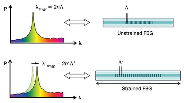
Figure 1. Optical fiber containing a Bragg grating illustrating the change in reflection peak of the grating in response to a perturbation such as strain. Courtesy of FBGS International, ©FBGS International, www.fbgs.com.
FBGs are optical fibers in which a short section — usually several mm — of the fiber core has been modified to produce a regular array of alternating micron-scale layers of differing refractive index. This grating becomes a strong reflector of light whose wavelength in the fiber exactly matches the “Bragg condition” of twice the grating period. Changes in the grating period and the fibers’ index of refraction can be monitored by measuring the wavelength of light reflected by the grating (Figure 1).
To measure rotating components without using the central rotation axis and enabling real-time monitoring of strain at fundamentally unlimited rotation speeds, researchers at Soreq Nuclear Research Center (NRC) in Yavne, Israel, implemented a short section of fiber containing the FBG and terminated it with a cylindrically shaped collimator. This fiber section is attached to the rotating structure with the collimator at the structure circumference facing outward. The FBG is probed via a second, static, lead fiber collimator, positioned externally at a convenient point such that the collimators will pass opposite each other once per revolution. During this transit time optical measurement may be made, while for the remainder of the revolution there will be no signal (Figure 5).
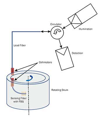
Figure 2. Schematic diagram depicting fiber-optic sensing in a rotating structure. The two fibers/collimators meet and exchange optical signals once per revolution. For simplicity only one sensing fiber with one FBG sensor is shown, although the concept can be extended to multiple sensing fibers around the circumference. Similarly, a sensing fiber may contain several different FBGs in series. Courtesy of Soreq NRC.
The research team verified its concept in a demonstrator system comprising an aluminum drum with a diameter of 150 mm, driven by a motor capable of rotating at controllable speeds up to 5000 rpm (Figure 3). Optical alignment of the system is performed using the two micrometer translation stages and two angular alignment screws attached to the static lead fiber collimator mount. The FBG section of the sensor fiber was glued to the inside surface of the drum, tangentially and at mid-height (Figure 2).
Measurements of the FBG reflection spectrum when the drum is rotating at constant speed are used to reveal the rotation-induced tangential strain in the drum, as a function of rotation rate. The optical system for measuring the FBG reflection spectrum is described fully in a recent publication6. The periodic detection of the reflection from the FBG occurs when the rotating sensor fiber collimator passes opposite the lead fiber collimator (Figure 4) — the transit time obviously shortens as the rotation speed increases. It is seen that at each rotation rate the FBG reflection signal has a temporal width that is a constant fraction (about 1/800) of the rotation period.
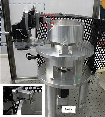
Figure 3. A demonstrator system for strain sensing in a rotating structure. The blue rectangle highlights the mechanical alignment of the external and stationary lead fiber collimator with respect to the sensor fiber collimator. Mounting of the collimators is achieved by V-grooves visible in the smaller frame, which is a magnification of the area denoted by the red rectangle in the large frame. Courtesy of Soreq NRC.
Registering peak reflections
For each rotation rate, the full reflection spectrum of the FBG has to be acquired, from which the local strain at the FBG location may be deduced. To this end, the optical source’s wavelength is scanned, while for each transient signal (Figure 4) the peak reflection and the instantaneous wavelength are registered. These are then plotted against each other to form the FBG full reflection spectrum for the given rotation rate. These spectra are measured by an optical spectrum analyzer with two-minute integration time for various rotation speeds (Figure 5). Note that the FBG reflection spectrum shifts to longer wavelengths as the rotation speed increases. The center of gravity (centroid) of each curve is used to quantify the shift as a function of the rotation rate. As expected, the time-averaged reflection intensity under rotation is about 800 times weaker than when stationary, due to the 1:800 duty cycle discussed above — i.e., the ratio between the time that signal can be measured (when the sensor fiber collimator passes across the lead fiber collimator) to the total period of rotation.
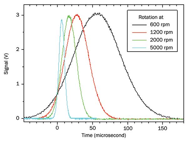
Figure 4. Transient signals reflected from the FBG under drum rotation at various rates. Courtesy of Soreq NRC.
The FBG spectral shift can only be due to strain induced in the rotating drum, because other parameters that can perturb the FBG reflection spectrum, such as temperature and pressure, were constant. The spectral shifts can be used to evaluate the strain induced in the structure on the basis of the fact that 1550-nm FBGs exhibit a strain sensitivity of 1.2 pm/µm strain7. Spectra such as that shown in Figure 5 were measured at rotation rates of 500 rpm intervals up to 5000 rpm, and the induced strain was determined on the basis of the magnitude of the FBG spectral shift from the stationary FBG spectrum. The strain increases quadratically with the rotation rate, as expected for a quantity derived from the centrifugal force (Figure 6).
Note that after the demonstration at rotation rates of up to 5000 rpm, the sensing fiber and FBG were undamaged and the experiment could be reproducibly repeated. This infers that the system and concept could be extended to even faster rotation rates.
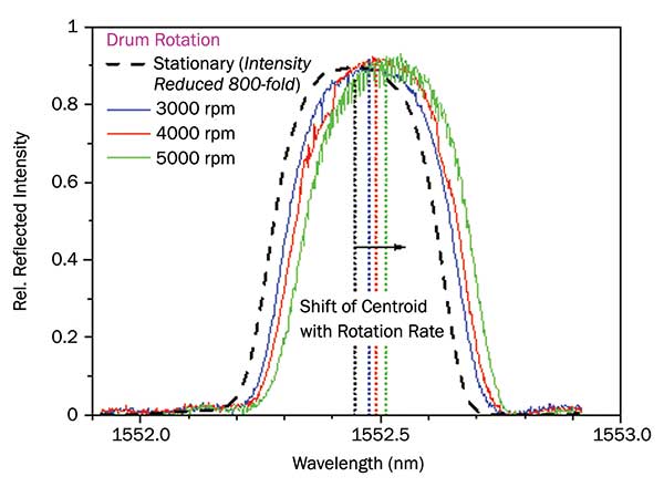
Figure 5. FBG reflection spectra at various rates of rotation showing the shift relative to the spectrum when the drum is stationary. Courtesy of Soreq NRC.
Simulating rotation rates
To validate the measured strains, the researchers performed numerical simulations with the commercial SolidWorks software from Dassault Systèmes. The calculation becomes much simpler if spherical symmetry of the rotating body is assumed, when just one slice may be modeled and information pertaining to the whole structure may be deduced. So for one rotation rate they compared results for both a full model and one assuming cylindrical symmetry (Figure 7), from which they deduced that to their needs the
symmetric model is sufficient: in both cases, at the FBG location (marked with red arrows), the strains are around 40-µm strain.
Based on this, the researchers continued with the “slice” calculation for the relevant rotation rates, with the outcomes superimposed on the experimental results in Figure 6 (dashed red curve). The theory and measurements agree very well.
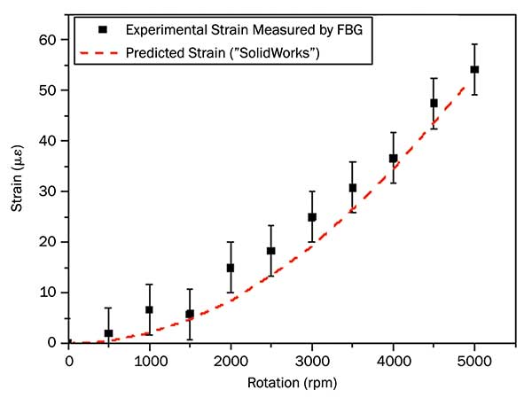
Figure 6. The tangential rotation-induced strain on the drum surface measured by the fiber-optic sensor compared to model predictions. Courtesy of Soreq NRC.
The above demonstration system used only one sensing fiber with a single FBG. However, the concept lends itself to multipoint sensing in either or both of two ways: (a) Use of multiple sensing fibers attached via collimators distributed symmetrically around the drum, and (b) Using sensing fibers with two or more FBGs in series along the fiber (a technique also known as FBG multiplexing2). In either case, each FBG will provide information on the local strain induced at the position where the FBG is attached.
Obviously, FBGs may be affixed at locations where the strain isn’t so straightforward, as was the above demonstration, like along helicopter blades, near the ends of wind-turbine blades subject to winds, inside vehicle or jet engines, etc. Other parameters like temperature and/or pressure may also be measured in the same way, as may be chemical and/or biological parameters2.
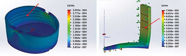
Figure 7. A full (left) and a ‘slice’ (right) strain calculation. The red arrow shows the FBG location, which is glued horizontally, at the marked slot, tangential to the drum wall. Courtesy of Soreq NRC.
Meet the authors
Ehud Shafir is a researcher at Soreq Nuclear Research Center in Yavne, Israel. He received his degrees in applied physics and electro-optics from The Hebrew University, the Weizmann Institute of Science and Tel-Aviv University, all in Israel; email: [email protected]. Shlomi Zilberman is a researcher at Soreq. He received his Ph.D. in physics from Tel Aviv University; email: [email protected]. Garry Berkovic is a researcher at Soreq. He received the B.Sc. degree in chemistry from the University of Melbourne, Australia, and his Ph.D. from the Weizmann Institute of Science in Israel; email: [email protected].
References
1. R. Kashyap. (2009) Fiber Bragg Gratings. Amsterdam, the Netherlands: Academic Press, ISBN: 978-0-12-372579-0.
2. A. Cusano and A. Cutolo (Editors). (2011) Fiber Bragg Grating Sensors: Recent Advancements, Industrial Applications and Market Exploitation. Oak Park, Ill.: Bentham Books, ISBN: 978-1-60805-343-8.
3. H.Y. Tam et al. (2005) Proc SPIE, Vol. 5634, p. 85.
4. J. M. Lee and Y. Hwang. (2008) Meas Sci Technol Vo1. 9, p. 065303.
5. Y. Chen et al. (2012) Proc SPIE, Vol. 8345, p. 834534.
6. S. Zilberman et al. (2015) Rev Sci Instrum 86, 115002.
7. E. Shafir et al. (2005) Smart Mater Struct, Vol. 14, N26-N28.
Acknowledgments
The authors wish to thank T. Goichman, M. Eizenshtat and O. Mazor of Soreq’s engineering department for the design and debugging of the demonstrator system, as well as performing the SolidWorks simulations, and Y. Saadi for technical support.