The metrology method should match the nature of the part and the inspection constraints.
AMY FRANTZ, EDMUND OPTICS INC.
The benefits of aspheric lenses are numerous: They allow for a reduction in spherical aberrations and are ideal for focusing or collimating light, as they can achieve a low ƒ-number. Aspheres also allow the same or better performance using fewer lenses, which often translates to a reduction in both size and weight in a system.
New applications in imaging increasingly require the use of aspheres, due to performance and size constraints. Manufacturing these surfaces requires equally innovative metrology methods. It is important to assess the strengths and weaknesses of the most common metrology methods that are used to quantify the surface accuracy of aspheres, and identify the criteria for selecting the most appropriate technique to measure specific classes of optical surfaces.
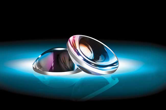
Aspheric lenses are designed to maximize performance in high-power Nd:YAG laser applications. Courtesy of Edmund Optics.
The interferometry that is typically used to measure the surface accuracy of optical components requires a planar reference wave to measure planar parts, or a spherical reference wave to measure spherical parts. Neither of these two approaches is ideal for measuring aspheres. The aspheric departure, or distance between the best fit radius of the asphere and its actual aspheric surface, creates very densely spaced interference fringes that are challenging to resolve. Because a spherical reference wave that matches the best fit radius of the asphere in question cannot always provide acceptable measurements, alternate methods to measure aspheric surfaces must be used.
To compare the performance of several asphere metrology methods, as well as the practical aspects of implementing their use in a production environment, consider the following methods:
• Contact profilometry, which records the position of a stylus as it traces a 2D path across the surface of a lens.
• Stitching interferometry, which combines multiple subaperture interferograms to create a complete, highly accurate map of the optic.
• Computer-generated holography, which performs standard interferometry on an aspheric component by using a computer-generated diffractive optical element to convert a spherical wavefront to an aspheric reference wavefront that matches the desired part profile.
• Chromatic confocal sensing, which illuminates a surface with a white light point source and senses the wavelength reflected from a surface to perform noncontact profilometry.
• Multiwavelength interferometry, which performs distance measurements using several discrete wavelengths to enhance the accuracy of surface reconstruction.
The above metrology techniques are all capable of measuring the peak-to-valley (PV) and root mean square (rms) accuracy of an optic compared to the nominal design. The key things to consider when selecting a measurement method are precision, speed of measurement, cost, and whether the part in question is within the geometrical space that can be adequately characterized by a given technology.
Stylus method suited for ground optics
In contact profilometry, a stylus is physically dragged across the surface of an optic. The other end of the stylus features a diffraction grating. Using the deflection of a laser directed toward the grating, the displacement of the stylus is recorded in a 2D trace. Contact profilometry is ideal for ground optics that do not reflect enough light to be measured with standard interferometry. Because the stylus is in contact with the optic, there are very few limitations to what shapes can be measured in terms of aspheric departure and points of inflection, although very steep slopes may not be measurable.
Contact profilometry has long been the industry standard to measure aspheric surfaces and it is cost-effective, but the method has some serious shortcomings: A single line through the center of a lens will not give an accurate depiction unless the errors in the lens are completely rotationally symmetric, which is rarely the case. This can lead to a misrepresentation of the part in question.
As an example, an interferogram of an actual lens is shown in Figure 1. Two traces are simulated: the first horizontally through the center and the second at a 45° diagonal through the center. Due to the astigmatism and other nonrotationally symmetric aberrations in this lens, the PV irregularity difference in these two values is greater than a factor of two. The rms values are similarly inconsistent. Although it is possible to take multiple traces at different orientations, this is time-consuming and will still lead to large untested areas. In some manufacturing protocols, it is necessary to have feedback on the surface accuracy of a part while it is in process, so that corrections can be made. Three-dimensional data is necessary to locate areas of excess material to be removed with deterministic tooling. In addition, because the stylus is in physical contact with the part, there may be a possibility of damaging softer materials or coatings if too much pressure is applied. For these reasons, it is advantageous to explore asphere metrology that derives its measurements from noncontact 3D surface profiles.
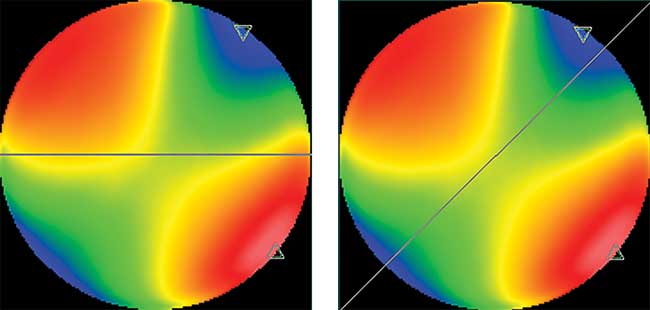
Figure 1. Interferogram with sample 2D traces. (Left) Horizontal: PV = 0.790λ, rms = 0.195λ. (Right) Diagonal: PV = 1.841λ, rms = 0.546λ. (PV = peak-to-valley, rms = root mean square). Courtesy of Edmund Optics.
Stitching interferometry is a common method of obtaining a profile of a lens. This method uses standard phase shifting interferometry on smaller subsections of the lens, and then uses software to stitch the pieces together. By gathering interferometric data from smaller subsections, a greater density of interference fringes over the surface of the optic can be interpreted. This is necessary because in addition to the fringes that arise from surface errors, aspheres tested with spherical wavefronts also produce fringes due to their geometrical departure from spheres.
In order to gather these data, one machine uses overlapping circular subapertures to form a complete map. Others may use concentric rings to form the total measurement. The machine is capable of removing its own system errors, so a highly accurate map of the surface can be achieved. Stitching interferometry is often limited by part geometry, and may struggle to measure lenses with large aspheric departure or steep slopes. Some lenses may require in the range of 100 individual subapertures, so measurement times may take upward of 20 minutes per part. It may be necessary to purchase a wide range of transmission elements with different focal lengths in order to accommodate a variety of geometries of the manufactured parts, and base units are costly.
Computer-generated holograms (CGHs) may be used to adapt an interferometer for use with aspheric surfaces. The spherical wavefront from the transmission element of the interferometer is altered by a CGH to form an apsheric wavefront that exactly matches the nominal optic surface profile. This is done by using a computer to fabricate a pattern onto a substrate that diffracts a wavefront to create a null reference wave. The surface accuracy that can be measured may be limited by the transmission element used with the interferometer or by the density of diffractive features that can be manufactured onto the CGH. A new CGH must be purchased for each asphere design, so this is a prohibitively expensive test method except when the same part is made in large volume. Once the CGH is aligned, testing a part can be completed in a few minutes, as only one interferogram is needed. CGHs are not able to test parts that have points of inflection and will not provide accurate data on the radius of curvature of the optic without additional precision location measurements of the test part along the optical axis.
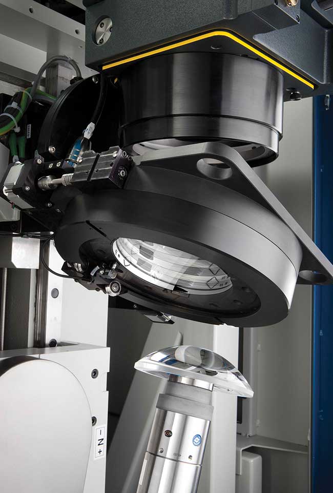
Stock optics can be customized by size, shape, and edges, improving the surface figure or accuracy of the optical surface. Courtesy of Edmund Optics.
Chromatic confocal sensing uses a chromatic pen that emits white light to take distance measurements. Due to dispersion, which is the difference in index of refraction in a glass based on wavelength, the focal length of an uncorrected lens will vary by wavelength. This causes different wavelengths of light to focus at different axial distances. Usually this chromatic aberration is an error that must be compensated for, but in chromatic confocal sensing, the effect is critical. Based on the wavelength of the light that is focused onto the sensor after it has made a return trip from the pen to the test optic, the distance to the optic can be determined. Chromatic confocal sensing allows great flexibility in the range of shapes that can be measured. Full hemispheres, large aspheric departures, and points of inflection will not pose a problem. Measurement of aspheric parts are likely to take around 20 minutes, and PV accuracies may not be much better than a half of a micron.
Multiwavelength interferometry uses the well-known practice of making length measurements with a single wavelength of light, and adds additional wavelengths to increase the accuracy of the measurement. Current units available have similar flexibility in shape to chromatic confocal sensing, but can achieve accuracies of a full surface to fractions of a micron in 2 to 3 minutes. The flexibility, precision, and speed of this method make it appealing if the project justifies a large monetary investment into the machine.
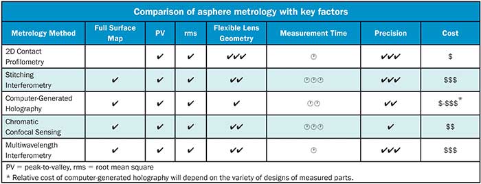
A comparison of the capabilities of the methods of asphere metrology discussed in this article is available in the accompanying table as a guide for selecting a machine based on the primary concerns of the operation.
The use of aspheres continues to grow in applications that have requirements including aberration minimization, high-resolution imaging with fewer optical components, and elements with low ƒ-numbers. Two-dimensional contact profilometry has long been the standard for measuring the surface form of aspheric optics, but as the demand for higher precision aspheres continues, so does the need for better asphere metrology that provides full 3D surface data.
With increasingly tight requirements for asphere surface accuracy, it is important to consider what method of asphere metrology is best-suited to the application at hand.