DAVID STADLER AND JOERG WERTLI, OPTOTUNE SWITZERLAND, AG
The use of laser light for materials processing has become a standard practice with widespread use in industry. The basic idea is to focus a laser beam onto a fixed working plane and create a spot of maximal intensity. At this position the laser processes the surface to drill, engrave or mark the work piece. Fixed glass optics, in combination with movable galvo mirrors, provide for the scanning of the whole working plane in horizontal X- and Y-directions. A typical scan field measures 100 × 100 mm. However this is restricted to one specific working distance (2D), whereas objects generally are three-dimensional (Figure 1).

Figure 1. Difference between 2D and 3D laser processing: The laser spot has to be adjusted in Z-direction to process the 3D work piece, as shown on the right.
In recent years, laser processing applications have sought to overcome this limitation and access the third dimension (Z-axis), typically by using mechanically moving Z-stages. In a complementary approach, Optotune has recently developed a tunable lens dedicated to laser processing, shown on the left of Figure 2. The lens has a 10 mm clear aperture and the optical coatings are optimized for 1064 nm laser wavelength. This enables 3D laser processing without any mechanically moving parts. Consequently, the time scale of focus change is very fast, in the range of several milliseconds.
Based on tunable polymer lens technology, the Z-position of the focus spot is changed by directly tuning the focal length of the tunable lens from −500 mm to +500 mm. The basic working principle of the tunable lens is illustrated on the left side of Figure 2. It consists of a container that is filled with an optical fluid and sealed off with an elastic polymer membrane. The lens core has an electromagnetic actuator that is used to exert pressure on the container, changing the deflection of the lens. This allows for controlling the focal length by changing the electrical current in the surrounding coils.
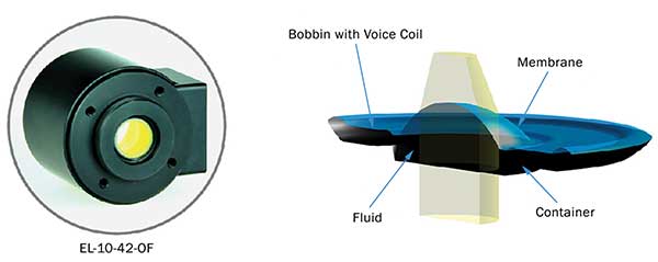
Figure 2. Tunable lens technology: The left side shows an image of the lens module and the right schematic illustrates the working principle of the tunable lens.
High focus stability and repeatability are essential parameters to guarantee consistent processing quality. If the laser is not focused on the working piece, the peak intensity quickly drops due to the increased spot size. Focus drift mainly originates from temperature effects. The volume of the fluid in the lens core slightly changes with temperature, leading to a change of deflection and focal length. That is why the technology presented has an integrated optical feedback that measures the deflection of the lens in-situ by detecting the probe light of an LED on highly sensitive photo diodes. Consequently, a position stability well below the Rayleigh length of a typical setup, the relevant figure of merit with which to compare, is possible. To further improve the long-term focus stability, the tunable lens is operated at a fixed working temperature of 47 °C. The internal heating element requires approximately 5 minutes to heat the lens after startup. Thermal isolation between external parts and the lens is ensured by a Teflon ring placed in between.
A controller card provides all the necessary analog and digital electronics to control the tunable lens. The hardware is optimized for the specific needs in laser processing applications, such as a minimal sized board and convenient interfacing to external electronics. To control the focal length of the tunable lens through the controller card, an analog voltage signal between 0 and 5 V is used. Through calibration, this voltage range has to be mapped to the tuning range of the laser spot in the Z-direction. This typically is done through a look-up table that maps a certain voltage to the corresponding Z-position (mm). This is, to a very good approximation, a linear relation. Furthermore, several digital signals for error handling are available, such as a “lens ready” signal. This can be used to trigger the laser at the right moment when the lens has reached its set point.
The small dimension of the technology presented allows for a very compact integration. A typical laser processing system provides enough space between the laser head and the galvo scanner for the tunable lens to be installed. As an application example, a table-top laser marking system has been set up. As a laser source, a 20-W fiber laser with a wavelength of 1064 nm is used. The beam has a diameter of 6 mm when entering the tunable lens. The galvo unit is a scan head with 10-mm sized mirrors. It is then guaranteed that the beam will not be clipped by the mirrors.
Two principle schemes of integration have been realized with the demonstration setup (Figure 3). On the left, the 2.5D approach with an ƒ-Theta lens of 160-mm focal length is shown. In this configuration the ƒ-Theta lens provides the field flattening at each Z-position while the Z-position of the laser spot is shifted by the tunable lens. The central working distance is at 191 mm and the resulting Z-tuning range of the system is about 100 mm.
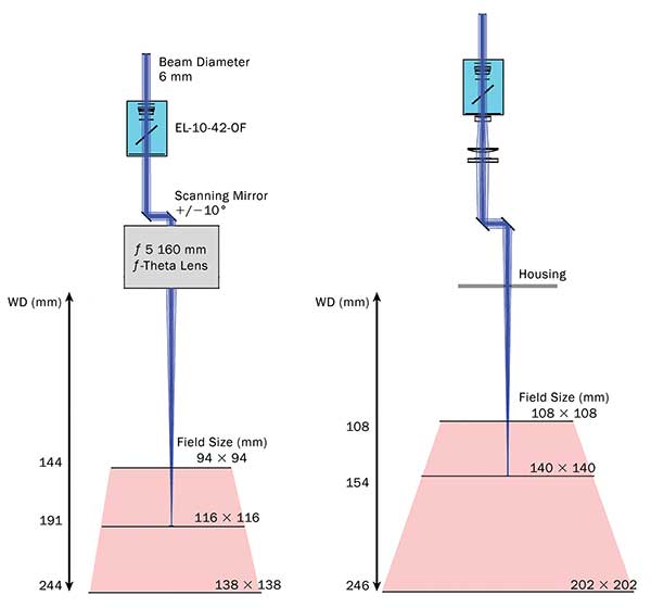
Figure 3. Two principles of integration: The left schematic shows the 2.5D setup with an ƒ-Theta lens of ƒ=160 mm focal length. The working distance ranges from 144 to 244 mm and the field size changes from 94 × 94 mm to 138 to 138 mm, set by the mirror angle of 20°. The right schematic illustrates a possible setup for ƒ-Theta free 3D marking. The tuning range and field sizes are larger compared to the system with ƒ-Theta lens.
It is important to note that the field size increases for longer working distance simply due to geometry. The tunable lens is placed in the optical path before the scan head. The exact position is not very critical because the distance between the ƒ-Theta lens and the tunable lens has only a very small influence on the available Z-tuning range. However, it is recommended to place the tunable lens as close as possible at the entrance aperture of the scan head.
The 2.5D system is a practical and simple solution when marking on horizontal layers at different heights. The time needed to jump from one layer to the next is a relevant time scale to quantify the marking speed. For a 10 to 90 percent step at the input corresponding to 0.5 and 4.5 V respectively, it requires approximately 12 ms to reach the new set point. The response time can be divided into two parts. First, there is a constant delay of about 3.5 ms due to the finite update rate of the analog-to-digital converters of the controller card. Then there is the rise time of about 8.5 ms to reach the new set point. For small steps the response time decreases to about 6 ms.
The integration for 3D marking is shown on the right of Figure 3. This approach is technically more appealing, but it is also more challenging. Field-flattening and Z-shift is accomplished by the tunable lens, making the ƒ-Theta lens unnecessary. The optical layout presented here is based on off-the-shelf lenses. Essentially, the tunable lens is followed by a beam expander and a focusing lens that creates the laser spot at a distance of 154 mm measured from the housing aperture. Due to beam expansion, the spot size remains roughly the same as for the 2.5D system with ƒ-Theta lens. However, the Z-tuning range and field size is larger. The implementation of 3D marking with an ƒ-Theta lens is also possible, but this approach lacks the advantage of reducing costs.
For highest 3D marking speed the different dynamical behavior of the tunable lens and the galvo scanner must be considered to guarantee synchronized operation. The tunable lens has a resonance frequency of about 200 Hz, resulting in a lower bandwidth than typical galvo scanners that can have a bandwidth of several kHz or more. This poses a challenge on both software and hardware integration to drive the combined 3D system at its physical limit. At present, on a surface that is tilted by 45°, a 3D marking speed of 700 mm/s can be achieved with the demonstration setup, limited both by software and the controller card. A desirable solution would be to have a fully digital controller board that controls all three axes at the same time or a separate controller with higher update rate and a digital interface. Such a solution is expected to increase the processing speed by factors, achieving typical speeds of standard 2D laser marking systems.
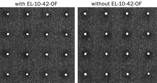
Figure 4. Comparison of marking quality with and without the tunable lens on anodized aluminum. When analyzing the 4 × 4 dot matrix under an 8× microscope, no significant difference is visible.
While speed is one aspect regarding the applicability of the tunable lens, the achievable processing quality is also important. This requires good optical quality of the utilized lenses, which can be quantified by the root mean squared (rms) wavefront error. The technology presented has a value of typically 0.15 of the laser wavelength, which is sufficient for many processing applications. With the demonstration setup Optotune marked a matrix of four-by-four dots on a plane. Each dot has a diameter of about 80 µm. The material used was anodized aluminum. Figure 4 compares the two situations with and without the tunable lens in the beam path. When analyzing the result under a microscope with 8× magnification, no significant difference is visible.
In a next step the optical design, software and control electronics have to be considered to achieve optimal performance in full 3D laser processing applications. First attempts in that direction are already initiated.
Meet the authors
David Stadler is an application engineer with Optotune Switzerland AG in Dietikon, Switzerland; e-mail: [email protected]. Jörg Wertli is the head of marketing with Optotune; e-mail: [email protected].