Dr. Peter Apian-Bennewitz, PAB Advanced Technologies Ltd.
Measurement of a material’s specific scattering properties takes the guesswork out of choosing materials for various applications.
Measuring the optical scattering of materials allows engineers to choose the very best materials for projects ranging from solar concentrators and LED lighting to architectural facades and instrument displays. The materials in question include glasses, polymers, metals, paints, IR-selective coatings, holographic diffraction films and structured surfaces in injection-molded parts. Scattering data, read by optical simulation programs, optimizes the internal composition and manufacturing process of the materials, providing a thorough analysis before manufacturing.
Here we will look at an overview and some examples of applied measurements of angular-dependent light scattering in the visible and IR ranges.
Measurement methods
A BSDF (bidirectional scattering distribution function; see box for definition and formulas) measurement setup consists of a light source, a sample mount and a detector. In a simple setup, all components are mounted “in plane” on an optical table, resulting in data along the scattering plane only; for the majority of samples, this is not sufficient.
Out-of-plane setups come in two varieties: Scanning goniophotometers move a detector mechanically around the sample, while imaging goniophotometers use additional optics (e.g., a semitransparent dome) to reflect light in various directions from a sample to the camera.
Dynamic range, homogeneous response, absence of secondary optics and optional polarization make scanning goniophotometers the primary reference instrument. Imaging goniophotometers are faster and therefore well suited for process control.
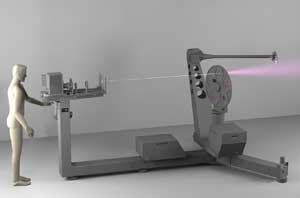
Figure 1. Optical scattering measurements allow engineers to choose materials more accurately for applications ranging from solar concentrators to instrument displays. A modern large scanning goniophotometer (here, pg II) is usable for a broad variety of samples.
Machines range in size from benchtop to room-size setups with 1-m distance between detector and sample. A larger distance r to the sample directly benefits a small solid angle of the detector, which is inversely proportional to r2. Modern goniophotometers (e.g., pgII in Figure 1) measure “on the fly,” without time-consuming start-stop movement of the detector. Their scanning velocity, in combination with a high sample frequency, allows fast, economic measurement times: For example, at 30 rpm for the two axes of the detector and 1-kHz sampling frequency, the angular resolution is still 0.18°. Lower speeds offer increased angular resolution, down to below 0.1 mrad.
Typical measurement times for one incident angle range from five to 20 minutes, resulting in a data set between 50,000 and a few hundred thousand data points for outgoing angles. Adaptive scan paths provide data points that are concentrated where they are needed most, with peaks in the BSDF more finely resolved than near-constant areas. This is crucial when measuring the small-angle scattering of mirrors, films or coatings. A detector head fitted with multiple sensors, taking data in multiple spectral bands simultaneously during one sweep, offers another convenient way to speed up measurements.
Absolute BSDF measurements (termed “absolute calibration” in ASTM E2387) use the incoming beam as reference, generating “ab initio” quantitative data without the need for a reference sample. The high dynamic range of the detector (eight decades, at least) makes this feasible, as my colleague and I showed in our 1998 article in Solar Energy Materials & Solar Cells.
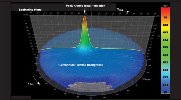
Figure 2. An example of a simple BRDF: semigloss paint with scattering around the forward peak and a near-constant diffuse background. In various kinds of paint, the relation between the forward peak to the diffuse background and the width of the forward peak defines the “gloss” of the painted surface.
The spectral range for BSDF measurements is limited only by a suitable detector and sources, ranging from UV into the infrared. Detector materials include Si, InGaAs or HgCdTe. Sources include halogen, xenon short arc and lasers at different wavelengths.
Visualizations
Data visualizations play an important role in comparing materials and in explaining a particular BSDF to a client. It is also very useful to cross-check simulations by comparing them with measured data.
To visualize the BSDF, which depends on four scalar variables, the two incident angles are kept fixed, and the reflective or transmissive part of it is plotted as a 3-D “mountain.” Figure 2 shows a reflective BSDF (termed bidirectional reflectance distribution function, or BRDF) with a frequently found shape: Light is scattered around the forward peak, the direction of the incident angle 5 outgoing angle, and the background is diffuse. In paints, the relation between the forward peak to the diffuse background and the width of the forward peak define the “gloss” of a painted surface: Matte paints have a high diffuse background and no or very broad peak, whereas high-gloss paints show a very small peak and low background (see examples at bsdf.pab.eu/paint).
Visualizations of the BSDF as seen in Figure 2 plot its value as height over a circular disk, using a linear or logarithmic Z-scale. Each point on the disk corresponds with one outgoing direction: The center plots the BSDF value for light leaving along the surface normally, and the circumference plots light leaving the surface tangentially. Angle Θout is plotted from center to circumference, and φout is plotted around the disk. (Note: This graph is better adapted to quantitative BSDF display than plotting “lobes” in spherical coordinate systems or Cartesian X-Y-Z systems.)
Applications
Usage of the BSDF typically includes the following:
(a) BSDF data is combined with models of surface- or volume-scattering whose parameters are fitted to the data. Surface models furnish data on the root mean square roughness of a surface; comparing this with directly measured roughness values (e.g., by atomic force microscopes) has been an area of active research. (F.E. Nicodemus and colleagues originally started the BSDF concept around 1970 to characterize highly polished mirrors in image-forming applications.) Volume-scattering models have applications in selecting polymer mixes used as diffusers in LED lighting applications, and in developing materials with different scattering in the visible and IR ranges.
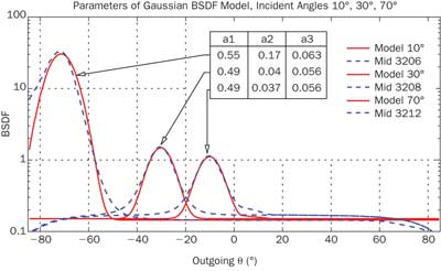
Figure 3. The combination of a Gaussian model for the scattering around the peak and a constant term for the quasi-diffuse background scattering, with the parameters of the Gaussian bidirectional scattering distribution function (BSDF) model (red lines) and measured data (dashed lines) for incident angles 10°, 30° and 70°. Note the change in parameters for larger incident angles.
(b) BSDF usage in optical simulation programs enables accurate calculation. For example, in illumination projects, taking into account specific materials for reflectors and diffusers optimizes the shape of a reflector regarding the BSDF of the reflector material, or the material selection for a specific shape. Most simulation software can read measured BSDF data to model surfaces that are not well described by built-in BSDF mathematical functions.
(c) The most straightforward use of BSDF data is comparing their plots directly. Projection screens are characterized by an angular factor of their BSDF relative to a diffuse screen, for example. Numerical integration of the BSDF over angular regions is the next step, resulting in transmission or reflection values in the interval (0:1). The direct-hemispherical reflection (pdh) and transmission (tdh) are extreme examples of integrating the BSDF over the full hemispheres, but the technique of numerical integration over parts of the hemisphere can do more, as shown below. Other quantities used by specific industries – the gloss parameters for paints, for example – also are numerically deduced from a BSDF data set.
Measuring the BSDF results in a complete angular data set containing more generic information than specific measurement setups such as Coblentz spheres, hazemeters and the like. It also provides a more comprehensive picture of the scattering, examples of which are shown below.
BSDF examples
1. Fitting parameters of simulation models to BRDF data: The data set of semigloss paint shown in Figure 2 can easily be used to fit simple model parameters in an optical simulation program. Figure 3 shows the resulting fit of a combination between a Gaussian model for the scattering around the peak and a constant term for the quasi-diffuse background scattering.
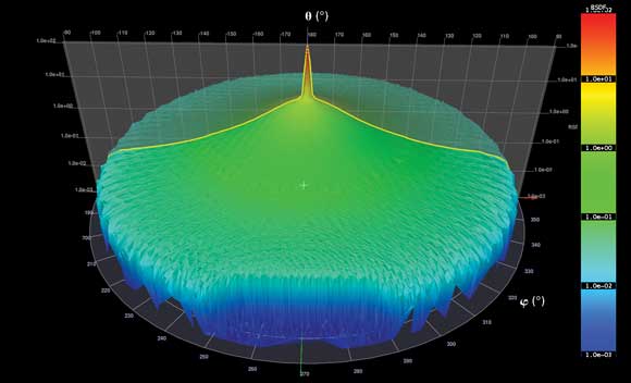
Figure 4. The BSDF of one polymer sheet used for LED lighting, at normal incidence.
The three parameters of the Gaussian model shown in Figure 3 are as follows: Hemispherical reflection pdh (a1) plus height (a2) and width (a2) of the Gaussian part. Note the typical increase of pdh and a2 with higher incident angle. Although the fit works well for incident angles 10° and 30°, notable differences exist between measured data and the best model BSDF for the incident angle of 70° (example data was taken from bsdf.pab.eu).
2. Selecting energy-efficient polymer blends in LED lighting: Diffusing elements for LED lighting achieve a uniform and glare-free light while maintaining the high efficiency of LEDs. Polymer blends are a suitable material with variable optical scattering.

Figure 5. The BSDF cross section of six polymer blends (top graph) and values of the integrated transmission.
Figure 4 shows the full BSDF of one polymer sheet (material A), and Figure 5 plots the BSDF of six different polymers. The BSDF shows a nonscattered forward peak and a falloff toward larger scattering angles. Integration of the full BSDF over a cone with opening angle a around the forward direction results in a set of curves in the lower plot of Figure 5. An opening of zero contains zero transmission, and a very small opening angle catches all light that is not scattered by the samples, which gives a rapid rise of the curve for materials with a strong forward peak. With increasing opening angle, the transmission increases monotonically, until it reaches the direct-hemispherical transmission (tdh) for α = 90°. Note that only this value would be available if an integrating sphere were used.
The integrated curve in Figure 5 now can be used to directly select the best energy-efficient material for a given application. For a project that needs the diffusing material to illuminate an area with an opening angle α = 12°, the best choice is material “D” (highest transmission into that cone), whereas an area with α = 32° would best be served with material “A.” This allows relevant materials to be quickly compared, sorted and selected. For a more detailed analysis, the BSDF is then modeled, and a full-fledged simulation using CAD models gives the detailed answer in the context of the application. Both ways are sourced from the full 3-D, out-of-plane BSDF measurement.
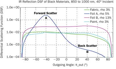
Figure 6. Infrared differential scattering function cross section of four black materials: one fabric, two adhesive foils and a matte paint, all visibly black, for an incident angle of 40°. Data was measured for the near-IR from 850 nm to 1000 nm.
3. “Black arts”: Black low-IR reflective surface materials that suppress stray light in optical equipment or displays should have an ideal BRDF of zero, or at least as low as possible for all incident angles and all wavelengths. Figure 6 shows the differential scattering function (BSDF*cos(Θout)) for one fabric, two foils and one matte paint, all visibly black, for an incident angle of 40°. Data in this case was measured for the near-IR from 850 to 1000 nm.
Three of these materials show a relatively flat angular response, with a value between 3 and 13 percent. Foil A has a low direct-hemispherical reflection but a higher value around 40° outgoing angle (A), since it scatters prominently into the forward direction. The choice of the optimal selection among the three low-reflectance materials depends thus on the application context: If a uniform low reflectance is needed, materials “paint” and “fabric” are a good choice. However, if backscatter toward the light source is to be minimized, foil A offers a much lower reflectance, backscattering about 50 times less than any other of these materials (indicated by B). Measured BSDF data offers useful insights into materials quickly.
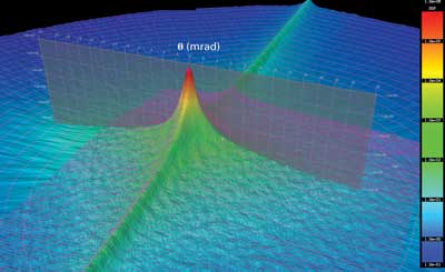
Figure 7. The differential scattering function of a mirror material for solar concentrators. Peak width at 1/10 of maximum is 1 mrad; dynamic range in data set is seven decades. To achieve the high resolution while minimizing speckle patterns, a spatially filtered, beam-shaped HeNe laser was focused on the detector aperture. Asymmetric scattering is observed due to a nonisotropic surface. The project involved multiple mirror materials and supports ongoing research to optimize concentrating solar systems.
4. BRDF of a mirror for solar concentrators: Figure 7 shows the finely resolved BRDF around the reflected peak of a metal mirror used in solar concentrators. The pink lines represent a series of data points taken while the detector moved and consists of 299,809 out-of-plane measurement points with an angular spacing below 0.1 mrad. To achieve the high resolution while minimizing speckle patterns, a spatially filtered, beam-shaped HeNe laser was focused on the detector aperture.
The data shows an asymmetric scattering due to a nonisotropic surface. The project involved multiple mirror materials and supports ongoing research to optimize concentrating solar systems.
Meet the author
Dr. Peter Apian-Bennewitz is managing director at pab advanced technologies Ltd. of Freiburg, Germany; email: [email protected].
References
F.E. Nicodemus et al (October 1977). Geometrical considerations and nomenclature for reflectance. Tech. rep., U.S. Department of Commerce, National Bureau of Standards.
Norm E2387-05, ASTM (2005). Standard practice for goniometric optical scatter measurements, www.astm.org.
J.C. Stover (1987). Overview of current scatterometer measurements and the impact on optical systems. Metrology of Optoelectronic Systems, SPIE Vol. 776, pp. 33-41.
P. Apian-Bennewitz and J. von der Hardt (1998). Enhancing and calibrating a goniophotometer. Solar Energy Materials & Solar Cells, Vol. 54, pp. 309-322.
P. Apian-Bennewitz (2010). New scanning gonio-photometer for extended BRTF measurements. Proc. SPIE, Vol. 7792, 77920O, doi:10.1117/12.860889.
M. Pharr and G. Humphreys (2004). Physically Based Rendering. 1st ed. Morgan Kauffmann, p. 1019.
Note
All BSDF/BRDF data used in this publication was measured using a pgII goniophotometer at pab advanced technologies Ltd.
BSDF definition
Within geometrical optics, energy transport by electromagnetic radiation is described in radiometric terms. The central quantity is called radiance, which is the power (watts) per solid angle omega (steradians) and radiating surface element A (m2), depending on a direction x from a surface element. Radiometric units could depend on additional parameters, such as wavelength or polarization, but do not include information on electromagnetic phase. Unless noted otherwise, they are integral over a specific wavelength range and all polarization states. If the spectral distribution is weighted with the standardized eye response V(λ), the quantities are called photometric (e.g., luminance instead of radiance).
Light scattering at a surface element is shown in Figure A: Incident radiation with radiance Lin is received by a surface element from a solid angle Ωin and scattered into a solid angle Ωin with outgoing radiance Lout. The scattering quantity depends generally on at least four scalar variables: two angles defining the incident direction, and two angles for the outgoing direction.
The central quantity for light scattering in this context is called BSDF, and it is implicitly defined by the integral given in Figure B. Mathematically, the BSDF is defined as a kernel folding the incoming angular radiance distribution into the outgoing radiation distribution. The implicit definition is robust, powerful and complete, as it includes all special cases. For example, an ideal transparent sample is described by a Dirac delta function of infinite height and infinitesimal width, which, by its definition, collapses the integral into a simply Lout = Lin in a mathematical, sound way.
A Dirac delta function δ(x – x0) has an infinite value at a single value x0 and zero value elsewhere. It integrates to one. This concept allows a mathematically formal way to write out idealizations and allows a formalism of handling practical cases that approximate the idealization closely.
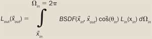
Figure A. The measured signal from any BSDF measurement device.
An ideal mirror is described by a similar Dirac delta function, whereas real mirrors are approximations to this ideally “thin” spike. Real mirrors, even highly polished ones, have a finite width of the BSDF since they scatter light in more then one single outgoing direction. This is relevant in imaging optics or, for example, with increased relevance in concentrating solar power systems.
A constant BSDF defines an ideal Lambert-scattering surface, which is the material of choice for the inner coating of integrating spheres and for diffusers. All existing “white standards,” typically made from sintered PTFE or barium sulfate, are an approximation to this ideally flat BSDF. Deviations from the ideal diffuser are routinely measured by national laboratories to calibrate diffuser standards.
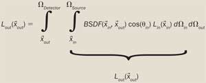
Figure B. The implicit, general and robust definition of the BSDF.
There is some discussion as to the usefulness of the cos term in the definition. Measurements and applications actually use the product BSDF*cos frequently. By standard ASTM E2387-05, this product is called DSF, or differential scattering function.
A more common, often seen, and yet mathematically inferior definition results by using ideal “parallel” incident light. This is itself described by a Dirac delta function containing only light from exactly one direction. Inserting this into the formula in Figure A, the explicit formula BSDF = Lout / Ein follows, with Ein being the incident irradiation onto the surface element. In fact, this definition is only marginally useful, since “parallel” light doesn’t exist; any light source at all subtends a finite solid angle. This has substantial practical consequences when measuring materials whose BSDF has an angular spread less than or nearly equal to the angular spread of the incoming light. Without taking into account the implicit definition of the BSDF, measured results would depend primarily on the incoming light and not on the material.
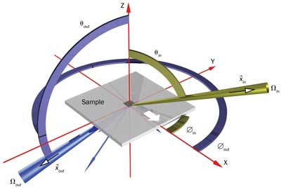
Figure C. The spherical coordinate system used for BSDF definition.
Additionally, because any measured signal is received by a detector that covers a finite solid angle on the outgoing side, a second integral over Lout in Figure A gives the measured signal. Figure B has all the pitfalls and problems of measuring a BSDF neatly written down. That is, the quantity of interest is inside two integrals, and only the result of the two integrals is known.
The solid angle Ωin, subtended by the light source, and solid angle Ωout, subtended by the detector, must be smaller than the BSDF angular detail one wishes to measure. They should be as small as possible while maintaining reasonable signal level. Collectively, the combination of beam shape and detector response is called the signature of an instrument, which is effectively a BSDF measurement without a sample.
A frequently used term is the scattering plane, spawned by the incoming direction and the surface normal. Since the reflected peak of an ideal mirror lies within the scattering plane, most 2-D plots show a cut of the BSDF along the scattering plane. However, for any but trivial materials, this should be accompanied by 3-D surfaces and/or multiple cuts through the BSDF.