Allan Jaunzens, Evatec Ltd.
Real-time technology helps manufacturers produce better thin films with less downtime, higher yields and lower costs.
From the simplest broadband antireflection coatings used on eyeglasses and camera lenses to the complex coatings used in civilian and military lasers, optical fiber devices and high-brightness LEDs, optical thin films are to be found everywhere. Although we may not be aware of their presence, thin-film coatings enable commercialization and efficient operation of optical devices that simply would not be possible otherwise.
Mass-production techniques including plasma ion-assisted evaporation and sputter already enable manufacture of high-quality optical layers. The thin-film engineer can select from a number of existing control techniques according to the optical application and the hardware installed on the manufacturing equipment, but these all have limitations. For some complex coatings in new emerging applications, even very small variations in deposition conditions may drastically reduce production yields. The time has come to add a new weapon to the arsenal of thin-film control techniques.

Figure 1. Quartz monitoring may be indirect because it doesn’t measure optical properties themselves, but it is easy to implement with simple operation and low hardware costs. Here, a quartz and optical monitoring head.
Industrial production tools that think for themselves have finally arrived. Such tools will integrate all the necessary steps from the first theoretical film design to creating and manufacturing a recipe with real-time automated re-optimization. The shorter development times, the increase in yields and the ultimate reduction of thin-film production costs could open up new cost-effective applications for optical coatings.
Conventional monitoring techniques
Quartz monitoring (Figure 1) is the simplest and most established technique for controlling thin-film layers. It relies on measuring the change in oscillation frequency of a quartz crystal as it is coated alongside the optical substrates. This change in frequency can be calibrated according to the type of material being coated and the equivalent film thickness calculated as deposition continues until the layer is terminated at the target value.
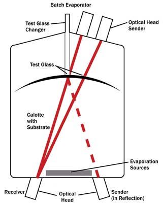
Figure 2. Optical monitoring offers direct measurement of optical performance, and test glasses can be retained easily for future reference. Here, an optical monitoring setup in a typical evaporation system.
Although “indirect” in that it doesn’t measure optical properties directly, the technique is easy to implement with simple operation and low hardware costs. Recent improvements using 6-MHz crystals and higher sampling rates have improved performance when depositing thin layers in particular, and quartz monitoring therefore remains a valuable measurement technique when overall stack designs are relatively simple and production tolerances fairly wide.
Optical monitoring
In its simplest form, optical monitoring involves measuring the intensity of light reflected from or transmitted through a test glass sitting alongside the substrate as it gets coated (Figure 2). The measurement is made for a specified wavelength by integrating a monochromator into the setup. Each layer is terminated as the measured intensity gets as close as possible to target maxima/minima precalculated for each layer using thin-film design software before the process starts. A new test glass can be selected for each layer of the coating, and the glass itself may be heated to simulate coating conditions seen by the substrates in hot processes.
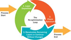
Figure 3. In online or in situ re-optimization, the first layer of the coating is deposited using broadband optical monitoring for termination. Then the actual measured reflection spectrum is compared with the precalculated target spectrum before real-time process changes are made downstream, if necessary. Here, a diagram of a re-optimization loop.
Relative to crystal monitoring, this technique offers the advantages of direct measurement of the optical performance and excellent signal-to-noise ratios, and the test glasses can be retained easily for future reference. However, hardware costs are an order of magnitude (or more) higher, and the user know-how required to get the best performance is much higher.
Broadband optical monitoring
Enjoying widespread use in the past decade particularly, broadband monitoring allows not just one wavelength but the whole spectrum to be checked. The “receiver” used in standard monitoring is replaced by a spectrophotometer with a temperature-stabilized CCD array. In some cases, it is possible to measure the actual substrate rather than a test glass to give the most direct feedback on the coating as it is deposited.
In typical comparisons with quartz monitoring using just single dielectric layers, the user could expect termination accuracies two times better using broadband optical monitoring. Although it is the most complex technique used in production to date, the enhanced accuracy translates into edge accuracies and repeatabilities of less than ±0.2 percent, even for complex multilayer coatings and nonconsecutive production runs.

Figure 4. In three case studies, thin films were coated using DC or mid-frequency AC sputtering. The system included plasma emission monitoring for control of reactive gas to enable high coating rates with low absorption and an optical broadband monitoring system for in situ direct measurement of the substrates. Here, a diagram of the experimental setup.
However, with ever-tighter tolerances demanded by new consumer and military applications, even these small variations in deposition conditions can have significant effects on production yield. Both standard and broadband optical monitoring approaches involve making a theoretical calculation about the optical performance of a particular thin-film stack design, working out a real process recipe, deciding what coating materials and layer thicknesses to use, making it and then testing the end result once the coating process is finished. At that point, it is too late to correct any small errors that might have occurred along the way, leading to losses in yield or even scrapped production in the case of unforeseen plant stoppage.
In situ re-optimization
In the case of online or in situ re-optimization (Figure 3), the first layer of the coating is deposited using broadband optical monitoring for termination in the normal way. But then a comparison is made between the actual measured reflection spectrum and the precalculated target spectrum. In the case of any deviations, the layer thicknesses and target spectra for the remaining layers are recalculated, and the process recipe for remaining layers is adjusted within a few seconds, avoiding any increase in production time. The next layer is deposited, and the re-optimization process is repeated until all layers have been deposited, ensuring that the final actual spectrum matches the target as closely as possible.
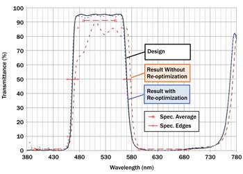
Figure 5. In the first test case, a 10 percent layer thickness in layer 13 was introduced artificially. Without online re-optimization, the final filter shows reduced transmittance and shifted edges.
This opens up new possibilities for improvement of spectral performance to new levels of accuracy, recovery after abnormal midprocess production errors to avoid lost batches, and commercialization of new complex processes where production yields otherwise would be too low.
Case studies
Three case studies for optical films deposited using both conventional broadband optical monitoring and the new in situ re-optimization method illustrate how production costs can be cut and output increased.
In the studies (Figure 4), all films were coated using DC or mid-frequency AC sputtering in a 1-m-diameter industrial production batch system with drum geometry. The system was equipped with plasma emission monitoring for control of reactive gas to enable high coating rates with low absorption, and optical broadband monitoring for in situ direct measurement of the substrates.
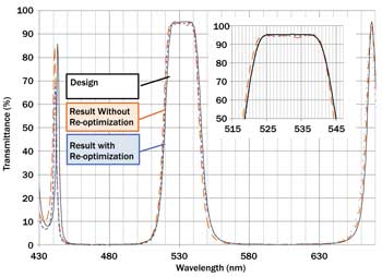
Figure 6. In the second test case, the production filter shows only a very small shift of 1 nm to shorter wavelengths and a small dip in transmission at 535 nm. However, with online re-optimization, even these very small deviations are corrected.
Case 1 – Recovery of unexpected production error: To simulate an abnormal production error, a 10 percent layer thickness in layer 13 was introduced artificially (Figure 5). Without online re-optimization, the final filter shows reduced transmittance and shifted edges. The filter does not achieve its production specifications, so the batch would have to be scrapped. If the same error is introduced and online re-optimization is activated, the coating system automatically calculates new thicknesses, and target spectra for the remaining layers and the final filter performance are well within specification.
Case 2 – Improvement in spectral accuracy: Standard optical monitoring achieves very good production results with good agreement between the original design and the actual measured spectrum of the end filter (Figure 6). The production filter shows only a very small shift of 1 nm to shorter wavelengths and a small dip in transmission at 535 nm. However, with online re-optimization, even these very small deviations are corrected.
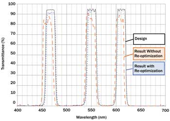
Figure 7. In the third test case, the high transmission in the blue, green and red required for this filter design are difficult to achieve with standard broadband optical monitoring. But online re-optimization enabled the coating system to make production-quality filters immediately.
Case 3 – Reduction in development times manufacturing costs: The high transmission in the blue, green and red required for this filter design are not easily achieved using standard broadband optical monitoring without time-consuming refinement of the monitoring strategy required for each layer termination. However, with online re-optimization, the coating system was able to produce production-quality filters immediately (Figure 7).
Meet the author
Allan Jaunzens is marketing manager at Evatec Ltd. in Flums, Switzerland; email: [email protected].