John Gilmore, Hamamatsu Corporation, and Dr. Slawomir Piatek, New Jersey Institute of Technology
A CMOS-architecture imaging array where each pixel is a photonic mixer device overcomes challenges in 3-D image capture.
Gauging the distance, size and shape of an object is of paramount and self-evident practical importance in everyday life. Nature has evolved a variety of ways for organisms to obtain 3-D information: stereoscopic vision utilizing two or more eyes, and sonar ranging are two examples. Extending this ability to inanimate systems such as robots, “decision makers” in automated assembly lines, or self-driving vehicles has been and continues to be an active area of research and development.
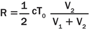
Among the several techniques that use light for measuring depth, two bear relevance to this article. In the first, the distance or range R to a point on the target surface derives from ΔT, the time it takes a pulse of light (for example, emitted by a laser) to travel from the observer to the point and back, namely R = cΔT/2n, where c is the speed of light in vacuum and n is the index of refraction of the surrounding medium. In the second technique, R derives from Δφ, the phase difference between the emitted intensity-modulated beam of light and its reflection; here, R = cΔφ/4πnf, where f is the frequency of modulation.
Prior to the mid-1990s, a 3-D camera employing either of these techniques required a mechanical scanning system to sample an array of points on the target surface. One limitation of such an arrangement is a compromise between the frame rate and density of sampled points, where the former affects the temporal accuracy of depth measurement for a moving target, and where the latter affects the spatial resolution of the features on the target. This compromise could have been lessened if it were possible to measure simultaneously all of the distances to an array of points on the target surface. This is now possible.
The breakthrough is the development of a CMOS-architecture imaging array where each pixel is a photonic mixer device (PMD). The upper panel in Figure 1 depicts a simplified structure of a PMD. An internal electric field directs the photogenerated charge carrier (electron) to one of the two charge storage locations. Two external signals, Vtx1 and Vtx2, control the strength and direction of the electric field, and they therefore also control how much charge each storage location receives in response to incident light. The output signals V1 and V2 are a measure of how much charge has been accumulated in locations 1 and 2, respectively. The lower panel of Figure 1 shows a simplified equivalent electrical circuit for a PMD. The main components are a photodiode (generator of photocharge), two capacitors (charge storage locations) and switches (responsible for directing the photocharge to the appropriate capacitors). A discussion of a more complete equivalent circuit and how it operates is below.
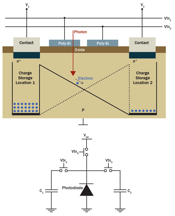
Figure 1. A simplified structure of a photonic mixer device (PMD) (top panel) and its equivalent electrical circuit (bottom panel). Photo courtesy of Dr. Slawomir Piatek.
In one common arrangement, a 3-D camera system illuminates the scene with an intensity-modulated infrared light. The optics of the system creates an image of the scene on the array of PMD pixels. For each pixel, the system determines an autocorrelation function between the electrical signal that modulates the emitted light and the electrical signals coming from the two capacitors. The system samples the resulting function four times per period, giving the phase shift, strength of the returned signal and the background level using well-known mathematical relations. The distance is proportional to the phase shift.
In the second arrangement, a 3-D camera system illuminates the scene with a pulse of infrared light of duration T0 (from ns to µs) while simultaneously making the pixels sensitive to light for the duration of 2T0. During the first half of 2T0, only one of the two capacitors collects the charge, whereas during the second half, only the second capacitor does. The distance imaged by a pixel derives from the relative amounts of charge collected by each of the two capacitors. A single pulse of light generally produces too little signal in the capacitors; thus, the system illuminates the scene with thousands of pulses appropriately spaced in time so that the capacitors accumulate enough charge to yield accurate distance. In literature, this type of 3-D camera is referred to as an indirect time-of-flight (I-TOF) camera, and the remainder of this article describes its operation in greater detail.
Principles of operation
Figure 2 explains the principles of operation of a single-pixel I-TOF camera, assuming one pulse of light per frame and the absence of background light and dark current. The shaded region depicts an equivalent electrical circuit of the pixel. The pixel consists of a photodiode whose output connects to three MOSFET (metal-oxide semiconductor field-effect transistor) switches: S1, S2 and S3. The first two connect to charge integrators C1 and C2, respectively, whereas the third connects to an external voltage source, Vdd. The timing circuit generates CMOS-compatible logic signals (Vtx1, Vtx2 and Vtx3), which drive the switches. A signal that is “high” turns a switch on, whereas a signal that is “low” turns a switch off. A dual-switch S4 shunts C1 and C2; the signal VR, also produced by the timing circuit, controls its operation. The pixel outputs two voltages, V1 and V2, per frame, from which the distance to an element of the target imaged onto the pixel can be calculated. For an array of (m, n) pixels, the camera determines m × n independent distances to the target elements, one for each pixel, per frame.
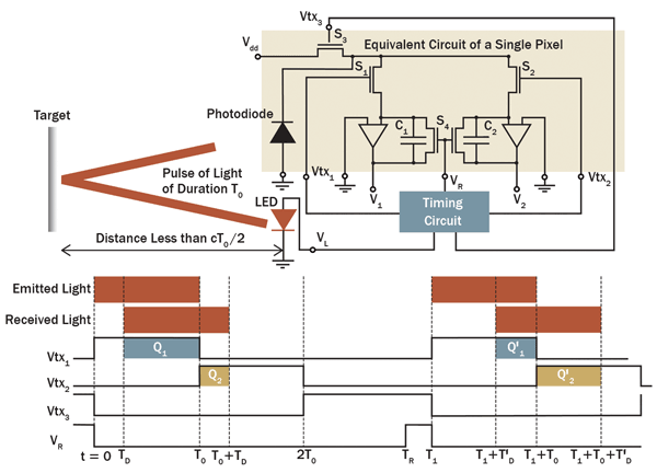
Figure 2. Principles of operation of a single pixel in an indirect time-of-flight camera.
To measure the distance to a point on the target, the timing circuit produces a signal (VL) that causes the LED or laser diode to emit a pulse of light of duration T0. Refer to the timing diagram at the bottom of Figure 2. At the instant of emission (t = 0), Vtx1 goes high, turning S1 on. The other three signals are low, keeping S2, S3 and S4 off. At t = TD, the leading edge of the reflected pulse arrives, and the photodiode begins to generate current, building charge Q1 and, thus, voltage V1 on the capacitor C1. At t = T0, Vtx1 goes low, turning S1 off; at the same time, Vtx2 goes high, turning S2 on. The signals Vtx3 and VR remain low, keeping S3 and S4 off. The photodiode continues to generate current, which now builds charge Q2 and, thus, voltage V2 on the capacitor C2. At t = T0 + TD, the trailing edge of the pulse arrives: The photodiode stops generating current and, therefore, Q2 and V2 have reached their final values, even though S2 remains on. At t = 2T0, Vtx2 goes low, turning S2 off, while at the same time Vtx3 goes high, turning S3 on. The switch S3 now holds the photodiode to Vdd, ensuring that (if present) both dark current and current caused by background light are prevented from flowing to C1 and C2. The camera system now samples V1 and V2, and calculates the distance using Equation 1.
The capacitors C1 and C2 hold their charge until t = TR, when the signal VR goes high, causing S4 to shunt and reset the capacitors. At t = T1, the camera is ready for the next frame.
Suppose that between t = 2T0 and t = T1 the target has moved to a greater distance. The timing diagram shows that for this frame, the charge Q′1 collected on C1 is less than Q1 and the charge Q′2 on C2 is greater than Q2. The resulting smaller V1 and larger V2 imply a greater distance for this frame, as expected from Equation 1. Since the smallest value of V1 is 0, the maximum distance that can be measured, R0MAX, is cT0/2.
The duration of the pulse limits RMAX. For a pulse with T0 = 30 ns and air as the medium, RMAX = 4.5 m. If the duration of a pulse is fixed at T0, RMAX can be extended by introducing a time delay between the instant the light pulse is emitted (t = 0) and the instant Vtx1 turns high (now at t = τ). Vtx2 turns high at t = T0 + τ, when Vtx1 turns low. Doing this extends the range in Equation 1 by cτ/2. The amount of light in a returning reflected pulse depends on the amount of light in the emitted pulse, the type of medium in which the pulse propagates, the distance to the target, and the color, orientation and smoothness of the reflecting surface. The amount is generally too small to yield an accurate measurement; therefore, thousands of pulses of light may be used for a single frame. Figure 3 is a simplified timing diagram depicting signals Vtx1, Vtx2, Vtx3 and VR for two consecutive frames, each produced from three pulses of light.
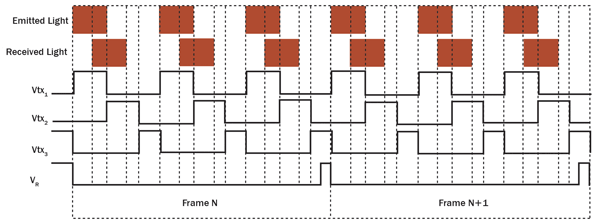
Figure 3. Timing diagram for two consecutive frames, each produced from three pulses of light. The target is stationary.
Many of the potential applications of an I-TOF camera require operation in full sunlight or under indoor artificial lighting. Background light carries no information about the target, and if it contributes charge to C1 and C2, the resulting distance measurement will be erroneous. Using a narrow bandpass filter centered on the wavelength of the emitted pulses suppresses the background but does not completely eliminate it. Dark current, continuously generated by the photodiode, has a similar effect on the distance measurement as a nonvarying background. Cooling the camera reduces dark current, but this approach may be impracticable.
To alleviate the effects of background and dark current, the camera obtains pairs of frames sequentially: The first “light” frame results from pulsed light, background and dark current, whereas the second “dark” frame results from background and dark current. Subtracting the “dark” frame from the “light” frame produces a “corrected” frame.
The top two panels in Figure 4 display scenes to be imaged with an I-TOF camera. In both scenes, the letters H, P and K are 1.0, 1.75 and 2.5 m, respectively, from the camera, but the hand is not. In the left scene, the hand is in front and close to the letter H, whereas in the right scene, it is in front and close to the letter K. The panels in the middle row are the corresponding-distance images acquired by a camera system using 10-μs pulses (3000 pulses per frame) from an 8 × 8 array of LEDs (λ = 870 nm, full width half maximum = 45 nm), IR-transmission filter HOYA IR83N, f/1.2 lens (focal length 8 mm), and a 160 × 120-pixel PMD imaging array (Hamamatsu S11963-01CR: pixel size 30 × 30 μm, field of view = 37.5° × 27.7°). The imaged distance is color-coded, with blue corresponding to the farthest and red to the closest. The panels in the bottom row show that the color (distance) of the hands becomes redder (smaller) as they are moved closer to the camera. How small a movement can a camera detect?
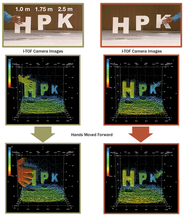
Figure 4. Example of an indirect time-of-flight camera output image with 3-D information.
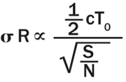
Equation 2 shows that the uncertainty σR in the measured distance by a pixel increases linearly with T0 and decreases as inverse square root with increasing signal-to-noise (S/N) ratio.
The noise (N) in the equation is a square root of the sum in quadrature of the signal (photon) shot noise (Nss), dark current shot noise (Nds), background shot noise (Nbs) and read noise (Nr). Equation 2 assumes that the target is at RMAX/2 so that the amount of charge accumulated by each capacitor is the same. If the photon shot noise is dominant, σR reduces to cT0/4√Ne, where Ne is the number of photoelectrons accumulated together by C1 and C2. Figure 5 is a plot of measured σR as a function of Ne. Here, the target is at R = RMAX/2, T0 = 30 ns, and there are 15,000 pulses per frame and no ambient light. The amplitude of the pulses is varied to achieve different values of Ne. The plot shows that σR decreases with Ne, as expected from Equation 2, and that the fractional error σR/R (R = 2.25 m) decreases from about 5.3% to about 0.44% as the collected signal increases from about 125 e− to about 275,000 e−. The more light there is, the more accurate the measured distance.
An achievable uncertainty of a few centimeters for a distance of a few meters is low enough for I-TOF cameras to find numerous practical applications. For example, the automotive industry has developed I-TOF camera systems that warn a driver (or take an independent action) about a possible frontal collision with an object such as another car or a pedestrian. Another use of I-TOF cameras is in robots that perform vision-based tasks in hazardous environments such as mines, mills or manufacturing plants. I-TOF cameras are used even in the entertainment industry: Video game developers have enhanced human-machine interaction in games requiring accurate distance information, such as virtual baseball, boxing or combat. By developing artificial and real-time 3-D vision, humans have finally caught up with what nature has been able to do for millions of years.
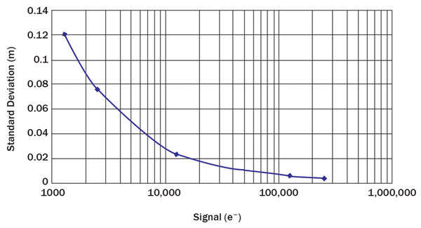
Figure 5. Distance uncertainty as a function of collected charge.
Meet the authors
John Gilmore is a technology manager at Hamamatsu Corporation; email: [email protected]. Dr. Slawomir Piatek is a senior university lecturer in the physics department at New Jersey Institute of Technology; email: [email protected].