TIM EMMERSON, PHOTONIC SCIENCE LTD.
Electro-optical systems that allow the hybridization of different imaging technologies can be seful, but may require a very complex integration effort. Challenges such as managing large amounts of real-time data and synchronizing multiple and differing imaging sensors can be overcome with emerging techniques and software development.
Machine vision traditionally uses imaging methods that are both spectrally limited, and of a fixed resolution and aspect ratio. The spectral limitation is often defined by the chemical makeup of the sensor being used (at the long wavelength end) and the optical lens being used (at the short wavelength end). Imaging systems traditionally use silicon and glass, making them spectrally limited to the 400 to 1125 nm region.
Imaging sensors based on other semiconductors can also be used — indium gallium arsenide (InGaAs), germanium (Ge) and lead (Pb)-based mixes — as well as detectors based on scintillation technologies, intensifier tube-based detectors and other nonintensified phosphor-based detectors.
These single sensor options give the end user a fixed detectable spectral range with which to optimize the imaging setup and also yield a fixed resolution, both of which can be seen as limitations.
Novel techniques involving hyperspectral multisensor composite systems and monospectral multiple image systems can be used to overcome these limitations. A third technique involving both different types of sensors, as well as multiple images from each of those sensors, is not discussed here.
Hyperspectral multisensor composite system A system that incorporates imaging sensors from different families, such as sCMOS and InGaAs together, can be used. This automatically increases the detectable spectrum available to the user by a factor of almost two, from just 725 nm wide up to 1300 nm wide.
In addition, a system can be designed that allows familiar scenes to be analyzed in a spectral region (i.e., x-ray) that augments the resultant monospectral image with valuable data that would be otherwise unavailable with a single imaging sensor (Figure 1).
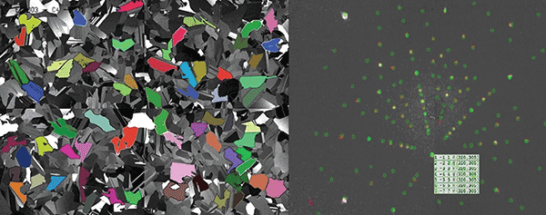
Figure 1. Silicon solar cell in false color, left, and x-ray crystallography data, right, (Laue pattern) from the same solar cell.
Monospectral multi-image composite system
This technique involves constructing a large scene using images taken with adjacent fields of view, by moving either the imager or the scene. This has the benefit of using a sensor to get very high intrascene resolution and also covers a very wide field of view (Figure 2).
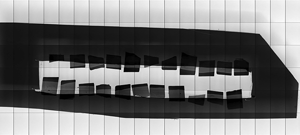
Figure 2. A 42-image mosaic demonstrates very high intrascene resolution and very wide field of view. This gives an image with approximately 76 MP and a field of view otherwise not possible with the use of one fixed sensor.
This is not possible using even high-resolution sensors behind wide-angle lenses.
A drawback is that the time taken to complete multiple image acquisitions and the subsequent stitching together to create a mosaic will typically preclude the use of this technique with dynamic (moving) scenes. The successively acquired “tiles” will differ too much for successful stitching at the edges, as the scene will have changed too much between the first and last image within the resultant composite image.
Limitations and problems
As with all complex systems, many different processes are required to work together at once in order to achieve a good end result. Any one of these processes failing or in some way not being optimized will impact other dependent processes, easily leading to a complete system failure (Figure 3).
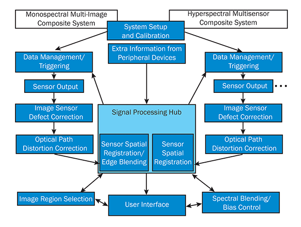
Figure 3. Descriptive diagram of the main processes in the two different types of systems: monospectral on the left, hyperspectral on the right. It can be seen that both system types make use of similar process blocks.
With both hyperspectral and monospectral system types, image data is acquired by multiple sensors, which is needed for cooperation between the two with regard to the time of acquisition. This is very important in a real-time hyperspectral system. Triggering the data acquisition is the obvious solution to this in either system, but a limitation would be the system data traffic/manipulation capability and also the individual sensor capabilities (frame rates). Both of these considerations can cap the system maximum frame rate.
Image sensor correction
Image sensor correction is one of the main cross-platform requirements. Image data must be manipulated to remove sensor defects specific to that sensor(s). These defects can be bright pixels, dark pixels and column structure (Figure 4).
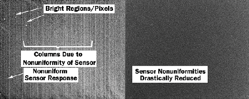
Figure 4. Raw image from a SWIR imaging sensor, left, alongside the output from the same sensor after the defects have been corrected, right.
Optical system distortion correction
Imaging systems need a lens of some sort between the scene and the image plane (sensor), and this will introduce distortions to the image that are not a faithful recreation of a real world scenario. These distortions are often very stable and so, at a cost of increased processing power and time, can be removed from the image as part of a correction process. The main distortions that can be corrected are barrel distortion and pincushion distortion, decreasing or increasing magnification of the image away from the image plane (Figure 5). A hybrid of the two effects is also possible.
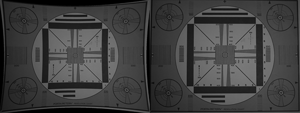
Figure 5. On the left is a test chart showing obvious distortion (pincushion), and on the right is the same chart corrected by software.
Chromatic aberration is also a problem in imaging systems, especially when very large spectral ranges are being focused through common objectives. Optical techniques can be used to reduce this (crown-flint pairs, catadioptric lenses), but these methods also have their drawbacks, such as limited spectral correction and restricted field of view. Chromatic aberration cannot be postprocess corrected any more than lack of focus can be, so intelligent optical system design and limitation recognition are the only solution to this.
Sensor registration
Another issue with these types of systems is registering the different images together (the actual processing is beyond the scope of this paper). There are many approaches to this problem, ranging from using very accurate and repeatable manipulation hardware (monospectral composite systems) to complex algorithms that use artifact detection techniques to register successive images together (hyperspectral imaging).
The main benefit of monospectral composite systems is arguably the potential for very high intrascene resolution with large images. An automatic, hands-off approach is always going to be more attractive than a labor-intensive manual manipulation of individual images to form a mosaic. In the case that the hardware used to manipulate the scene or the imaging device is sufficiently accurate and repeatable, a simple approach of adjoining successive images is applicable, but with the increased cost of very high-end hardware and the complexity limitations of the hardware type possible.
The table below demonstrates the cost and benefits of the different solutions available to reposition the imaging sensor in monospectral multi-image composite systems.
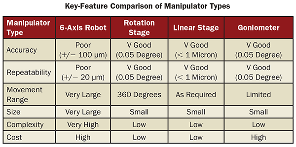
This table demonstrates the cost and benefits of the different solutions available to reposition the imaging sensor in monospectral multi-image composite systems.
In a hyperspectral multisensor composite system, there is a unique problem with the compilation of the images from different spectral regions. In a scientific application, this issue is somewhat negated by the culture of analysis that comes with it; raw data alone can often be presented to the user as the need for actual images can be reduced (Figure 1).
In many cases, however, and nearly always in the nonscientific arena, hyperspectral image data needs to be blended into single frames for viewing. This is not how the world is normally perceived and to do it as such can cause the resultant images to become too cluttered and artifact-dense.
Specific approaches need to be considered and used to blend the hyperspectral images together.
As the available grayscale/color palette will be set by the viewing part of the imaging system, using grayscales out of the fixed range is not possible. Allocating swathes of the existing dynamic range for extra spectral data can be considered, but is a drawback for a user needing to differentiate between closely spaced grayscales. Allocating the brighter parts of the image to one sensor and the darker parts to another is exceedingly confusing for the user, as well.
A false color approach that overlays color over monochrome images (or vice-versa, depending on the required bias) is arguably the most intuitive method.
Along with this, if processing power is available and the application method is suitably robust, using image analysis to make the user aware of salient information in real time is another approach. This does rely on the analysis of the hyperspectral input to be trusted as it is not being viewed by the user until it becomes software-deemed relevant.
User interface
Designing the user interface for a multi-camera system is a very important step to complete correctly. By falling at this hurdle, all of the technology behind the scenes is made redundant; if the user doesn’t understand what they are looking at, the whole imaging system can actually prove to be a hindrance.
In a simple system where there is only one scene per viewing device, the center of the image is usually designated for the center of the monitor, as this is where lenses perform best. This still holds for compound, hyperspectral systems where the center of the lenses will essentially line up. But since multi-image composite images do not benefit from this, the periphery of the lens involved in each snapshot will always be seen. Registering images together with redundant overlaps will reduce the inherent, noncorrectable lens effect at a loss of total resolution.
System improvements, future enhancements
All systems can be improved upon. The main processes that can be further optimized by advances in technology are the data management system frame-rate image sensor defect correction and the user interface.
More capable data protocols (USB 3.1, OCuLink) will allow progressively more data to be moved around efficiently.
Further increases in the computing power of CPUs will also yield faster image processing, as will the trend toward using GPUs (CUDA-enabled GPGPUs) to process images at ever-increasing rates.
Increasing the sensor(s) frame rate may be achieved by using multitap sensors in order to get the image data from high-resolution sensor(s) more quickly.
All of this, coupled with innovative user interfaces (HUDs, immersive goggles), will lead to higher frame rate and hyperspectral, high-resolution imaging systems that do more to educate the user about the environment than ever before.
Meet the author
Tim Emmerson is a research and development project manager at Photonic Science Ltd., in East Sussex, England; email: [email protected].