Software can help a design move quickly from proof of concept to production.
Michael Zollers, Optical Research Associates
Designers often are faced with the daunting task of translating vague requirements for a complex device into a set of design specifications for individual components. Then they must use those specifications to create a working design. Each decision must be weighed carefully because early decisions affect the design space of components specified later.
How would you proceed if you were asked to design a small, but bright, projector system? Would you use a digital micromirror device (DMD) or liquid crystal displays (LCDs) to spatially modulate the light? What type of light source would you use?
A DMD is a good choice because the polarizers needed for proper operation of the LCD introduce a 50 percent or more reduction in the amount of light that gets through the system. A high-luminance source such as an arc lamp is required to compensate for this loss. The requirement for a small system means that using a source large enough for use with LCDs isn’t possible. Depending on the source, one DMD can be used, or a three-DMD system is possible — one of each color channel (red, green and blue).
There are many options for the light source, including halogen, arc sources and LEDs. For a small projector, a halogen source cannot be used because it produces too much heat. An arc source would provide the highest luminance, but it requires a ballast and can be large. The white light of an arc source would require dichroic filters in the light path to separate the red, green and blue colors. The color separation could occur with a filter wheel, but moving parts are undesirable in small devices that may travel in a briefcase or carry-on luggage. When using an arc source, both single-DMD and three-DMD designs are possible.
LEDs could be used in a small, bright projector system, but they have their own limitations. The driving electronics are small, but LEDs produce a lot of heat, so adequate heat sinking must be incorporated into the housing design. White-light-emitting LEDs do not have the luminance to power adequately a projector that will be used in a room with ambient light; therefore, the projected image would be too dark. However, because LEDs are available in the colors red, green and blue, a three-DMD design is possible.
Making the imaging system telecentric in object space can make the design of the imaging optics easier and can remove some relative illumination issues inherent in off-axis designs. However, forcing telecentricity in a DMD system can cause geometric problems in the illumination portion of the design.
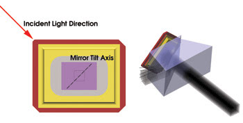
Figure 1. The DMD mirrors tilt on a 45° axis, forcing the DMD to be rotated with respect to the prism.
Figure 1 shows the heart of the issue: The individual mirrors of the DMD, manufactured by Texas Instruments Inc. of Dallas, tilt along a line that is 45° to the long side of the DMD. This off-axis tilt causes the illumination to be misaligned with respect to the sides of the chip. Prisms typically are used to correct for the off-axis behavior in single-DMD designs, but the DMD is rotated 45° with respect to the illumination direction. The entire illumination system must be rotated back 45° so that the projected image is aligned to the horizon. This derotation greatly increases the size of the entire projector package. To keep the projector small, a prism that doesn’t require the DMD rotation is needed. In the three-DMD design, telecentricity becomes even more difficult. Several patents1,2 have been issued that describe methods for making a telecentric three-DMD system.
Choosing a light source
There are still several design directions to consider: an arc source with one or three DMDs, or LEDs with three DMDs. I would evaluate the LED system first, specifically Osram Ostar LEDs. Most LED manufacturers do not have a red, green and blue LED with identical die geometry because the short-wavelength colors (i.e., blue and green) are made with a die material different from that of the longer-wavelength LEDs (i.e., amber or red). The differing die materials lead to different die geometries, which lead to dissimilar intensity distributions. LEDs with different sets of output distributions require varying collection optics for each color channel. However, the Ostar LEDs are tailored specifically for projection systems and have very similar die geometry for all colors. The nearly surface-emitting nature of the die also can help with the design of the collection optics.
With most of the specification settled, the rest of the design can be considered. A prism is needed to create a telecentric output when the DMD mirrors are tilted to the “on” state and to create a completely dark output when the mirrors are tilted to the “off” state. The mirrors tilt ±12° between states. LightTools design and analysis software can create the geometry and simulate the optical performance of the system. For this, the DMD is modeled using solid geometry whose dimensions are available from a data sheet. The individual mirrors are modeled using physical geometry applied to the chip surface as a user-defined 3-D texture. The tilt state is set using a numeric parameter; with this feature, you can change a single numeric parameter in the model to tilt the mirror to the “on” state, to the “off” state or to the “ground” state.
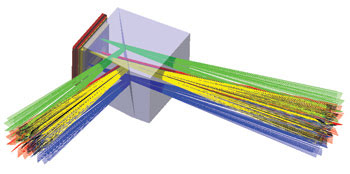
Figure 2. Light enters the prism from the left, experiences total internal reflection off the air gap and reflects off the DMD into the imaging system (not shown).
The prism has an air gap between the two halves that causes total internal reflection (Figure 2). The shape of the prism is specified fully by three parameters: the input angle for the prism and the two tilt angles that define the surface at which total internal reflection occurs. Pickups are defined throughout the model geometry to ensure that whenever one of the three input parameters changes, the entire prism rebuilds correctly. This type of parametric modeling is especially useful when used in conjunction with optimization. With this prism design, the DMD is aligned with the prism, so no derotation of the system is required.
The LED collection optic requires a uniform, rectangular spatial luminance output distribution with the same aspect ratio as that of the DMD. Thus, the optic needs a maximum cone angle of 12° (the deflection angle of the DMD mirrors). The output of the four individual die of a single Ostar LED can be mixed to form one superimposed distribution, or the output of each die can be tiled spatially. If the die outputs are tiled, the system should include a feedback mechanism that monitors and adjusts the power of all four die; otherwise, if the power of one die drops with respect to the other three, the output distribution will be nonuniform. If the outputs of all four die are superimposed onto one another, the system becomes tolerant to individual die output fluctuations.
A square or rectangular tapered coupler works well as an LED collection optic. The next step is to model the solid plastic piece making up the optic using a skinned solid in the design and analysis software. The dimensions of the input and exit faces are specified, and the software builds the intermediate geometry. In this case, simulating the effect of only one die is necessary. Because the system is symmetric with respect to the die positions, if one die creates a uniform distribution at the output, the output of the entire system is uniform. The shape of the skinned solid can be optimized to increase the efficiency and uniformity of the output, but for the proof of concept, a straight taper is sufficient.
All that remains is to put all of the pieces together and to see how the system performs. An X-prism can multiplex the output of the individual prisms, and simple lenses can image the output of the LED optic onto the DMD. A set of complex folded optics will make the overall projector package small, but, for simplicity, an unfolded system is shown in Figure 3.
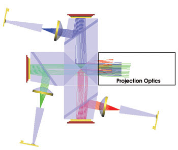
Figure 3. Software aided in the design of this complete unfolded proof-of-concept projector system.
With a simple design completed, it is time to reflect on some of the choices made during the design process. Is this the best design? Can this design be used as a starting point for a more optimized design? If so, should all of the components be optimized concurrently or individually? By parametrically modeling the system with software from the onset, further optimization of this design is easily done. For example, maybe this system using LEDs and three DMDs is larger and less efficient than a design with a single DMD and an arc source. The next step is to create another proof-of-concept design and to compare it with this one. Several alternatives could be considered, and by considering external drivers such as manufacturing constraints and by utilizing virtual prototypes of the optics, the design can move quickly from proof of concept to production.
Meet the author
Michael Zollers is a senior optical engineer in marketing at Optical Research Associates in Pasadena, Calif.; e-mail: [email protected].
References
1. US Patent 7,118,225. Oct. 10, 2006.
2. US Patent 7,144,116. Dec. 5, 2006.