A fiber optic interrogator based on optical time-domain reflectometry predicts and prevents geological hazards.
Navneet S. Aulakh, Central Scientific Instruments Organisation, Council of Scientific and Industrial Research, Government of India, and Dr. R.S. Kaler, Thapar Institute of Engineering and Technology
Loose sediment, rocks and weathered material usually remain stationary and stable on a slope. However, matter can be disturbed naturally by earthquakes or heavy rainfall, or by human activity such as road construction. When disturbed, the debris is pulled down by gravity and, with water acting as a lubricant, a landslide is created. The damage can be disastrous — wiping out communications networks or causing damage to life and property — but the good news is that, unlike other geological hazards, landslides can be predicted with technology.
Many options are available for monitoring landslides. In-place inclinometers, extensometers and tiltmeters can detect new movement as well as direction and acceleration of movement. Unfortunately, tiltmeters and inclinometers are cumbersome to install, time-consuming to operate, lacking in sensitivity and susceptible to environmental hazards.1
Another recently developed technique for landslide monitoring is based on time-domain reflectometry.2 This technology uses coaxial cable and a cable tester; however, it suffers from errors in readings caused by water seepage and electromagnetic interference.
By design, optical time-domain reflectometry that uses fiber optics instead of coaxial cable is inherently immune to electromagnetic interference and moisture ingress.3 For this technique, the fiber optic receiver converts the light intensity from the optical fiber into an electrical signal (Figure 1). This is amplified and given to a filter circuit, which conditions the signal for input to the analog-to-digital converter. From there, it’s sent for analysis to the microcontroller, which fixes the threshold dynamically and monitors the input signal. If the input falls below the threshold, the device issues a warning through an audio-visual alarm, and the relay is operated.
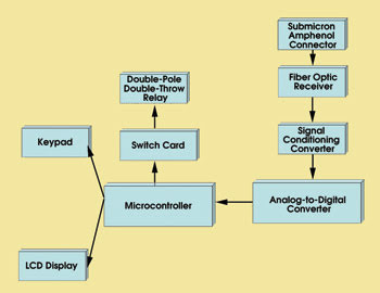
Figure 1. This block diagram of a fiber optic interrogator shows how the signalreceived from the fiber optic sensor is converted to an electrical signal and then digitized and analyzed to generate a warning in the event of a landslide.
Fiber optic sensor
If a portion of fiber is deformed by movement of land mass, the fiber exhibits excess light loss. Such perturbation of the fiber axis results in redistribution of guided power between modes of the fiber and in coupling of the fiber from one mode or mode group to another. In ray description, because of sharp bends in the fiber, some light rays will fall at the core-cladding interface at an angle that is less than critical, thus preventing total internal reflection. These rays will be lost from the guiding structure.
As the fiber is bent more and more sharply, an increasing number of rays will be lost. The bend loss becomes steeply dependent on bend radius at a certain point, as defined by the fiber’s geometrical characteristics. The microbend sensor uses this property to launch constant light intensity into the fiber from one end. The light that reaches the other end is measured continuously. When there is relative movement of soil mass, as happens with a landslide, the fiber is bent, causing light attenuation, and the fiber optic interrogator at the other end sounds an alarm.
Experiments were performed at an active landslide site near Mansa Devi Temple in Uttaranchal, India. At landslide-prone locations, a fiber optic interrogation system was installed, along with the conventional instrumentation. The idea was to fix the thresholds by comparing the data obtained from the fiber optic interrogator with that from conventional instrumentation such as the tiltmeter, inclinometer, etc.
The fiber optic sensor installed along the hill slope has a microbend-resolution enhancer with a reel for holding about 10 m of fiber enclosed in a biconical casing, which was used at the flagged points (Figure 2). Typically, a force of 5 kg was applied at the junction of the two microbend-resolution enhancers to simulate the effect of a landslide. The sensor cable shown is 20 m long, so it is sufficient to monitor the bulk of the landslide’s movement. The cable length can be increased according to the size of the area to be monitored.
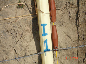
Figure 2. A close-up view of the fiber optic sensor shows specially designed anchors installed along with the conventional inclinometer casing.
The interrogator takes the digital input corresponding to the perturbation and sends it via serial ports for logging (Figure 3). Testing of the system was carried out under stable conditions and during measured perturbation. The logged data was graphed and analyzed. Because there were no short-term variations in the slope, the data collected compares well with that from the conventional instrumentation. When the fiber was subjected to perturbation, the system sounded an alarm, and the data showed a corresponding change in the level of light intensity measured.
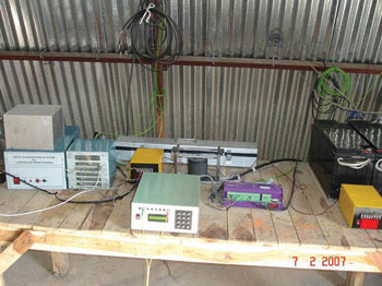
Figure 3. The fiber optic interrogator was installed in a makeshift shed. Solar panels provided the power source.
Using a fiber optic system for monitoring landslides promises to be an economical alternative to conventional instrumentation. The change in the rate of movement can be determined by plotting the fiber attenuation slope with time. Advantages of such a system over the traditional methods include the following: easy installation, less time-consuming data collection, disposable cable, no need to clean debris from the inclinometer hole before taking measurements, immunity to electromagnetic interference, no negative effects from moisture in the cable and the ability to monitor remotely from multiple locations using data loggers and modern communications facilities.
References
1. J. Dunnicliff and G.E. Green (1988). Geotechnical instrumentation for monitoring field performance. Wiley-Interscience, pp. 209-273.
2. W.F. Kane and T.J. Beck (1994). Development of time domain reflectometry system to monitor landslide activity. Proc. 45th Highway Geology Symposium, pp. 163-173.
3. N.S. Aulakh, J.K. Chhabra, N. Singh, S. Jain (May-June 2004). Microbend resolution-enhancing technique for fiber optic based sensing and monitoring of landslides. Exper Tech, pp. 37-42.
Meet the authors
Navneet S. Aulakh is a scientist with the Central Scientific Instruments Organisation of the Council of Scientific and Industrial Research in Chandigarh, India; e-mail: [email protected].
R.S. Kaler is a professor at Thapar Institute of Engineering and Technology in Patiala, India.