Full company details
Nufern
A Coherent Co.
 7 Airport Park Rd.
East Granby, CT 06026
Phone: +1 860-408-5000
Toll-free: +1 866-466-0214
Selecting the Optimal Er/Yb Doped Optical Fiber: Design Considerations and System Performances
The goal of this tutorial note is to provide the reader with the proper tools to understand the principles of light emission in Er/Yb fibers and related design considerations. This article should serve as a guide for the users to select the optimal Er/Yb fiber in order to achieve the highest output performances within their system requirements.ClÉmence Jollivet & Kanishka Tankala
General Er/Yb fiber amplifier architecture
Er/Yb double-clad (DC) fibers are used in laser or amplifier systems for power scaling and/or single-frequency applications. Depending on the system architecture and the targeted output power and efficiencies, the choice of the fiber design is critical. To illustrate this statement, a typical Er/Yb fiber amplifier is schematically represented in Figure 1. It starts with a seed light source emitting in the 1.55 μm wavelength range with 100 mW or less available power. These are generally commercially available modules such as a laser diode or a narrow-linewidth distributed feedback grating (DFB), operating in continuous or pulsed regime, with or without polarization maintaining (PM) properties. The seed light is coupled in one or more fiber amplifier stages. Each amplifier is made using a DC Er/Yb fiber - one or multiple 9XX-nm pump modules via the use of multi-legs fiber combiners (set in co- or counter-propagation) and additional devices such as polarization optics and optical isolators.
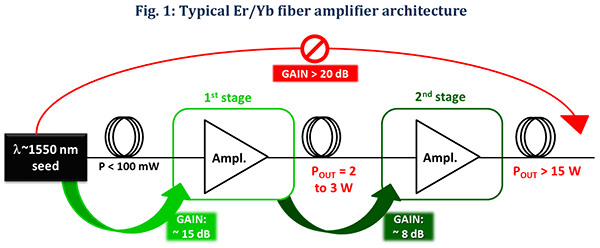
Figure 1. A light source typically emitting 100 mW of output power or less is amplified by one or more fiber amplifier modules made with Er/Yb fibers. Various schemes can be chosen depending on the target output power (POUT) while the achievable amplification levels are indicated with green arrows.
The number of amplifier modules depends on the target output power and ultimately on the extractable fiber gain. In Figure 1, two common cases are distinguished corresponding to target powers of (
a) a few Watts or (
b) a few tens of Watts. Achieving a few Watts output power requires an amplifier able to deliver 15 to 18 dB optical gain. It is common to associate these amplifiers with only one pump module delivering on the order of 10 Watts of power. In this case, the best Er/Yb fiber candidate must perform with ultra-high efficiencies and low amplification threshold in order to extract the maximum gain for a fixed pump power. On the other hand, different applications require tens of Watts of output power. In this case, the required optical gain is well above 20 dB. Operating in such regime must be avoided since it favors the apparition of parasitic ASE and non-linear effects which affect the stability of the amplified light and inhibit the output performances. Therefore, scaling the output power above tens of Watts is achieved employing 2-stages amplifier architecture as depicted in Figure 1. The few Watts output power from the first stage are used to seed the second stage along with multiple pump modules. The Er/Yb fiber best suited for second stage amplifiers must deliver high efficiencies while inhibiting parasitic effects such as the 1 μm ASE.
Amplification mechanisms in Er/Yb co-doped systems
When pumping Er/Yb fibers with 9XX-nm pump wavelength, population inversion occurs within the Yb energy levels. In a well-designed fiber, the rate of energy transfer from the excited level of Yb to an excited state of Er is faster than the decay time from the excited state of Yb ions to the ground state. In other words, emission will occur within the Er band resulting in amplification around the 1.55 μm wavelength range. If the energy transfer is not efficient enough, then the energy decay will occur within the Yb atoms energy levels resulting in parasitic emission in the 1 μm wavelength range first with ASE, followed by self-lasing.
These concepts are illustrated in Figure 2 in terms of output power (Figure 2(
a)) and in terms of emission spectrum (Figure 2(
b)). Figure 2(
a) schematically represents the characteristic output power (P
out) evolution as function of the launched pump power (P
launch) in the Er/Yb fiber amplifiers. As P
launch increases, the measured input seed (P
seed) increases linearly, indicating light being amplified. The efficiency of the amplification, labeled η, is quantified by the slope of the linear increase as defined in Figure 2(
a). It is important to note that, in Er/Yb amplifier and laser systems, there is a minimum pump power required to initiate the amplification (or lasing respectively). This minimum power is called the system threshold and is labeled P
th. A typical emission spectrum under 940 nm pumping is presented in Figure 2(
b) with the green line. Above a certain P
launch value, parasitic emission arises from the decay of Yb atoms, from the excited state to the ground state, resulting in ASE signal in the 1 μm wavelength range. Non-optimized Er/Yb fiber designs exhibit stronger parasitic signals. This phenomenon is illustrated in Figure 2(
a) where parasitic ASE (dotted red line) increases above a certain pump power resulting in a roll-over of the 1.55 mm emission. Typical spectra are shown in Figure 2(
b) and represented the parasitic 1 μm ASE (red line) which transforms into self-lasing at higher pump power values (red dotted line). With the apparition and increase of light in the 1 μm wavelength range, the system faces competitive emission phenomena. In practice, this has a dramatic impact on the seed amplification and results in a power drop or roll-off. In addition, the self-lasing 1 μm light becomes particularly dangerous since the system becomes exposed to several back-reflections which will irreversibly damage the amplifier.
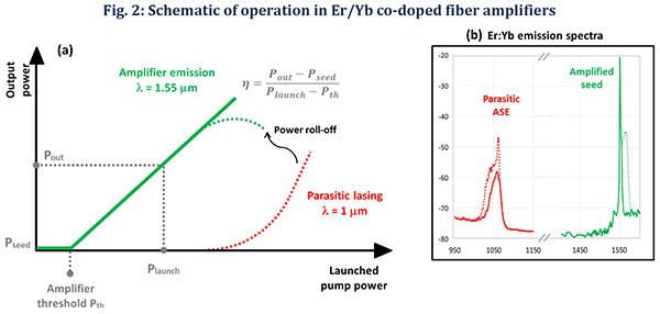
Figure 2. (a) Schematic representation of the amplification (green) and the important parameters such as the threshold power (Pth) and the efficiency (η). Parasitic effects are also shown (red). (b) Typical emission spectra showing the 1.55 μm amplification (green) and the 1 μm parasitic effects (red).
Therefore, efficiency, threshold and parasitic 1 μm ASE must be closely monitored in order to characterize the amplifier and/or laser system. Depending on the application, performances in terms of linewidth, birefringence, and pulse duration, etc., might also become critical. However, these parameters are beyond the scope of this application note. There are several degrees of freedom that can be adjusted in Er/Yb fibers such as the composition of the core and the structural design (size, shape, etc). Different combinations of these parameters result in very distinct performances.
For example, larger core sizes lead to higher efficiencies (until gain saturation) at the expense of the single-mode (SM) properties of the output beam. Large-mode area (LMA) designs offer simultaneously large core and SM beams. However, the pedestal region surrounding the core requires (a) finely tuned splicing procedure to ensure low-loss coupling and (b) proper coiling to couple the higher-order modes (HOM) from the core to the pedestal. On the other hand, the core composition must be finely tuned to provide the best performances. Each improvement comes at the cost of another parameter. For instance, maximizing the efficiency and minimizing the threshold usually results in higher 1 μm ASE levels. On the other hand, minimizing the 1 μm parasitic effects will penalize the threshold.
Therefore, selecting the optimal Er/Yb fiber composition, design and manufacturer is critical as it will determine the output performances of the system in terms of efficiency, threshold and 1 μm ASE.
Single-stage Er/Yb amplifier using Single-Mode EYDF “XP” products
To reach a few Watts of output power, the amplifier must be designed with an Er/Yb fiber optimized for high extractable gain and high efficiencies. Generally, one pump module emitting up to 10 W of 9XX-nm light is used. Nufern offers a family of Er/Yb co-doped DC fibers labeled EYDF and has developed a product called SM-EYDF-6/125-XP, optimized for single-stage, few-Watts output power amplifier and lasers. This is a 6 μm core diameter, single-mode fiber designed for ultra-high efficiencies and low threshold, ideal to reach a few Watts of output power (gain > 15 dB) with a limited pump power (around 10W). Nufern has tested this fiber in an amplifier configuration and measured results are displayed in Figure 3.
For these tests, we used a 1.55 μm seed light emitting 100 mW of output power (Pseed) and one pump module at 940 nm light wavelength. The pump diode was fiber-coupled in a 105 μm core and 125 μm cladding diameter step-index fiber which was fusion spliced to the SM-EYDF-6/125-XP via a fiber combiner. The maximum pump power available was around 10 W. The EYDF was wrapped around a metallic mandrel of 10 cm in diameter, sitting on top of a cool surface for thermal management. The EYDF output was angle cleaved to prevent facet lasing of the emission. Using an appropriate set of spectral filters, we recorded the efficiency and threshold of the amplified seed at 1.55 μm and the amount of 1 μm parasitic light.
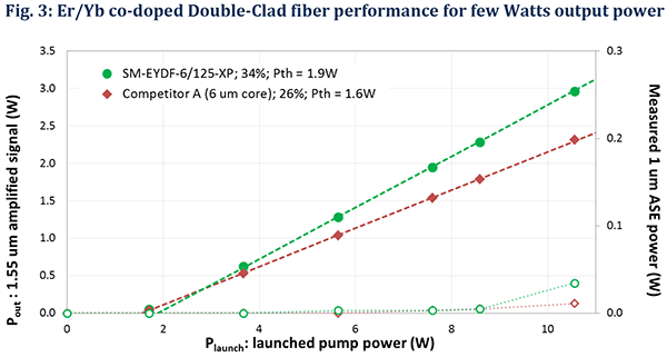
Figure 3. Measured performance of Er/Yb fibers in a single-stage amplifier system. The efficiency, threshold (left y-axis) and 1 μm parasitic emission (right y-axis) have been recorded for Nufern’s SM-EYDF-6/125-XP (green) and a 6 μm core fiber labeled Competitor A (red).
The plot in Figure 3 shows the seed amplification (full green markers, left y-axis) and the parasitic 1 μm emission (empty green markers, right y-axis) measured as function of the launched pump power. Using the SM-EYDF-6/125-XP fiber, we were able to achieve an efficiency of 34% (42% as function of absorbed pump power) with a threshold around 1.9 W of Plaunch. For comparison, we tested a different fiber, labeled Competitor A (same core size as SM-EYDF-6/125-XP) on the same test bench. Measured data are plotted in Figure 3 showing 26% efficiency (full red markers) and 1.6 W threshold power. As Nufern’s fiber composition is optimized for high efficiency, the level of 1 μm light generated remains below 50 mW in both cases (which is below the damage limit for such system).
These results confirm that the fiber design, in particular its core composition, has a significant impact on the output performances. It is thus critical to choose the Er/Yb fiber carefully depending on the application requirements. Nufern offers a product (SM-EYDF-6/125-XP) which is optimized for few-Watts amplifier levels.
High power and second stage amplifiers using Multi-Mode and LMA EYDF “XPH” products
The preferred approach to scale the output power above 15 W is to use a second stage amplifier made using Er/Yb fibers with 10, 12, 25 or 30 μm core sizes. Higher output power levels are enabled using larger core sizes. The ideal fiber design for such application is optimized to deliver high efficiencies while inhibiting the 1 μm parasitic light generation. Nufern has designed a suite of optimized Er/Yb fibers to reach stable operation at 20 W output power and beyond. Here, we present a summary of the performances for our 10 μm core (MM-EYDF-10/125-XPH) and the 12 μm core (MM-EYDF-12/130-HE) fiber products. PM and LMA versions of these fibers are available on demand. Also, 25 and 30 μm core size fibers are available for single-frequency and further power scaling applications above 100 W.
Using similar amplifier system architecture as described in the previous section, Nufern has tested the MM-EYDF-10/125-XPH and the MM-EYDF-12/130-HE fibers. Results are plotted in Figure 4(a) and (b) respectively. For this second stage experiment, we used 6 pump diodes at 940 nm wavelength providing a total pump power of 47 W. The input light from the first stage amplifier was used to seed the high output power amplifier stage. A total input power of 1.4 W was selected for these measurements. As a side note, it is possible to use higher seed power which is expected to result in higher efficiencies and higher output powers without degrading the 1 μm parasitic light. We were able to achieve 40% and 41% efficiency with the 10 and 12 μm core fibers respectively (green markers in Figure 4(a) and (b) respectively) corresponding to 18 W of output power. In the case of the 12 μm fiber, these measurements were pump limited. While efficiencies are comparable to fibers from Competitor B and C, the inhibition of 1 μm parasitic effects is quite remarkable in MM-EYDF-10/125-XPH and MM-EYDF-12/130-HE compared to their direct competitor. In Figure 4(a) one can see a significant increase of the 1 μm light above 18 W of launched pump power for Competitor B (blue filled orange markers). In this regime, the amplifier output power become highly unstable due to the self-lasing phenomenon at 1 μm with a high risk of permanent damage in the long run. A similar result was measured for Competitor C compared to MM-EYDF-12/130-HE, limiting the achievable output power at 8W and 10 W in Competitor B and C respectively. Our optimized EYDF products offered more than 18 W of output power which was pump limited emphasizing the importance of the fiber choice in Er/Yb systems.
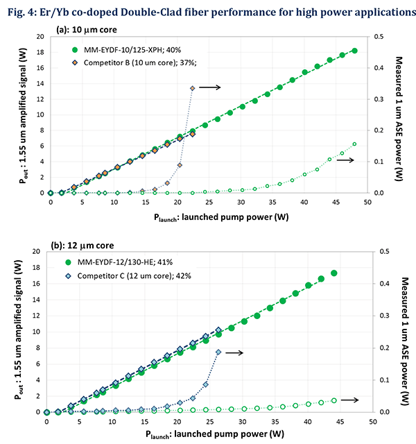
Figure 4. Measured performance of Er/Yb fibers for high output power applications. Presented results summarize efficiency (left y-axis) and 1 μm parasitic emission (right y-axis) for (a) 10 and (b) 12 μm core fibers. Performances are compared with fiber from competitor B and C respectively displayed with blue/orange and dark blue markers.
Summary
Er/Yb fibers are well suited to achieve high performances in the 1.55 µm wavelength range, allowing to reach a few Watts to Watt-level of output power. However, we demonstrated that these performances are directly tailored by the core composition and the structural design of the fiber. The key to success is to clearly identify the target output performances and to choose the most appropriate fiber design.