By observing a few simple rules that govern diode lasers’ properties, driving them loses much of its mystery. Below its threshold current, a diode laser emits LED light with spontaneous emission only. At the threshold current and above, it begins to generate laser light, and the optical output power rises steeply with increasing diode operating current. The correlation between the optical output power and the diode current is linear up to the maximum power, called differential efficiency (Figure 1).
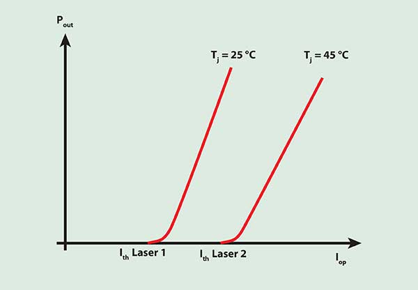
Figure 1. The output power of a diode laser is a function of the operating current. Pout = output power; I = current; th = threshold; T = temperature; j = junction (the place where laser radiation originates in the laser chip); Iop = operating current driving the diode laser.
An often overlooked factor in handling diode lasers is the influence of temperature on the relationship between optical output power and operating current. While the threshold current raises with temperature the optical output power and differential efficiency decrease. The driver circuit thus should have a safety feature that ensures that a significant temperature increase will not destroy the laser.
Not an option
Any driver circuit for diode lasers should include a well-filtered power supply that, as efficiently as possible, blocks inductive loads and other sources of interference. Battery operation circumvents the problem but is not an option in many industrial applications. Keeping the connections between the diode laser and the driver circuit short generally will help reduce interference.
Integrated driver circuits offer a variety of functions and safety measures, and they require few additional components. A simple resistor trimmer can usually set the operating point. It is important that diode lasers always have a regulated driver in either automatic current control or automatic power control operation. A standard laboratory power supply is not suitable for driving them directly.
The diode laser’s wavelength varies with temperature. For a typical GaAlAs diode, this is about 0.25 nm/°C, gradually combined with sudden steplike jumps (mode hopping).
In automatic current control operation, precise temperature control yields the best stability for optical output power. Because of the diodes’ temperature dependency, the temperature must be regulated to maintain constant keeping it from exceeding critical values.
In industrial applications — such as light barriers and distance-measuring sensors where the ambient temperature varies — automatic power control systems typically offer simplicity of operation. Conventional automatic power control driver circuits also have soft-start circuits, filter spikes, overvoltage and other transients.
Seeking constant power
A power regulator guarantees a constant output. When the temperature remains unregulated, however, wavelengths can shift and mode hopping can occur. Even in applications where this does not pose a problem, there should be sufficient thermal dissipation. Without it, rising temperature — through self-heating, for example — will cause a decrease in efficiency. The regulator circuit compensates for this with an ever-increasing laser current in an attempt to keep the output power constant. Without a current limiter or safety shutdown circuit, the diode could be damaged or even destroyed.
Automatic power control employs a monitor diode integrated into the laser package for feedback. Lasers with integrated monitor diodes are available in three configurations, all with the common terminal connected to their housing, which is often electrically connected to ground. The output from an integrated monitor diode is not suitable for calibration. At a given output power, the monitor current may vary by a factor of 10 from laser to laser.
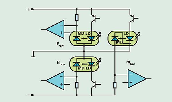
Figure 2. The three available diode laser configurations, P-, N- and M-type, require different driver principles. MD = monitor diode; LD = laser diode.
Configurations must be taken into account when selecting a driver circuit because each type requires different driver principles (Figure 2). The N-type diode needs an output driver from a negative supply voltage and a minus-referenced monitor current input. P-type diodes require an output driver from a positive supply voltage with a monitor input connected to plus. An M-type diode must have a dual supply with a driver output from plus and a minus-referenced monitor current input. Each of these three variants needs its own optimized driver configuration. Some driver devices include connections for two or even all three variants. The one limitation, however, is that the laser diode package cannot always be connected to ground, as it is in the illustration.
Keeping cool
In most applications and in continuous-wave operation in particular, a heat sink is essential to prevent an excessive rise in chip temperature and thus damage to or destruction of the diode laser. A low operating temperature generally lengthens the life expectancy. Statistically, a reduction of 10 °C in the operating temperature doubles the lifetime.
Even if the laser is driven by a suitable integrated driver, the assembly of the setup requires great care. A driver device that doesn’t have a safety shutdown circuit or current limiter can cause damage from over-current, when a line interruption in the monitor path is taking place. One should never disconnect the driver and the diode laser via a switch or relay. The various driver devices have respective functions for spike-free power up and power down and for pulsing of the laser diode.
Either an automatic current control circuit combined with a temperature regulator or an automatic power control unit is required to guarantee maximum lifetime and stable operation. Even tiny increases above the threshold current can bring about a considerable increase in output power and a rapid over-shoot of the optical output power critical value. Cooling measures in both automatic current and power control setups are imperative for stable operation and long laser diode lifetimes.