Researchers around the world discover new techniques and materials that increase grating size while also increasing the laser-damage threshold.
Bruno Touzet and Dr. John R. Gilchrist, Jobin Yvon Inc.
Over the past 20 years, the use of chirped-pulse amplification has enabled lasers to produce powerful pulses in the femtosecond and picosecond time regime.
The development of higher-energy lasers is hampered by a major limiting factor. In general, the compression stage of chirped pulse amplification is based on diffraction gratings — two gratings usually working by reflection. Higher-energy lasers require larger, high-efficiency gratings, but laser-induced damage remains the main obstacle to the realization of such lasers.
The traditional holographic gold-coated diffraction gratings for pulse-compression applications work either at 1.053 μm or around 800 nm. These present many useful features, including a diffraction efficiency that can reach as high as 95 percent and a reflected wavefront quality of λ/6 or better (Figure 1).
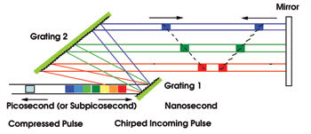
Figure 1. In this schematic of a chirped-pulse amplification technique, two diffraction grating pairs are used.
Even at this high efficiency, users are obliged to limit the power of their laser to prevent damage to the gold reflective layer and to the grating itself caused by the very high power density of the compressed beam. There are two ways to reduce the potential damage to gratings: increase the grating size to reduce the power density or develop new grating materials that have a significantly higher damage threshold than gold.
Jobin Yvon Inc. is equipped to manufacture large gold-coated pulse compression gratings in dimensions of up to 600 mm. Because of the physical limits of size and weight (and also the cost implications of producing huge gold-coated master gratings), company researchers in Longjumeau, France, have studied new materials and developed a manufacturing technique to directly engrave the grating grooves inside the uppermost layer of a high-damage-threshold multilayer dielectric coating. This avoids the use of a gold coating on the grating surface.
For many years, multilayer dielectric structures composed of alternating high- and low-index layers have been known for their high reflectivity. They also present a much higher damage threshold than metallic gold layers. Recent optical calculations have shown that, if one engraves a diffraction grating inside the upper layer of the multilayer dielectric structure, diffraction efficiency might reach 99 percent.
Two years ago, with help from researchers at Laboratoire pour l’Utilisation de Lasers Intense (LULI) and Ecole Polytechnique in Palaiseau, France, we began engraving gratings inside multilayer dielectric structures and demonstrating the advantages of this technique. Today we produce large-area, multilayer dielectric diffraction gratings for laser chirped-pulse-compression applications on a commercial basis. These new technologies have the potential to change the high-energy, ultrahigh-speed, pulsed laser market.
Classical gold
It’s interesting to analyze the performance of gratings for pulse compression using classical gold-coated and ion-etched gratings inside a multilayer dielectric coating obtained in a 100-TW glass chirped-pulse amplification setup. From the mid-1980s, this technique has demonstrated that it is possible to obtain highly efficient transverse magnetic polarization laser light with a sinusoidal profile holographic grating coated with gold.
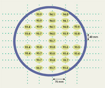
Figure 2. This efficiency map of the grating shows the excellent uniformity in diffraction efficiency obtained across a large-area pulse compression grating.
In this respect, efficiency calculations, performed in collaboration with the laboratory, demonstrated that a sinusoidal grating with 1740 grooves per millimeter is a good choice for optimizing efficiency at 1.053 μm. Absolute efficiency on transverse magnetic polarization can be as high as 95 percent. Following this, chirped-pulse-amplification gratings with 2000, 1480 and 1200 grooves per millimeter were produced with similar efficiencies. Performance was measured on a 1740-grooves-per-millimeter grating with a 400-mm diameter, optimized for 1.053 μm (Figures 2 and 3).
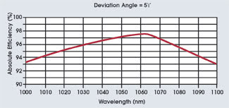
Figure 3. The theoretical efficiency of a sinusoidal groove profile holographic grating coated with gold was calculated.
Measured efficiencies approximate the theoretical efficiencies and are homogeneous over the surface of the gratings, and λ/6 quality diffracted wavefront has been achieved. The typical damage threshold in the right-hand section of the beam of the holographic gold-coating grating is 2 J/cm2 in the nanosecond regime and 1 J/cm2 in the picosecond regime.
We first conducted a theoretical study of a new structure of diffraction gratings engraved by ion etching in the upper layer of a high-laser-damage-threshold dielectric multilayer coating. We found various configurations with 100 percent efficiency for both selected alternatives: high-index (hafnium oxide) and low-index (silicon oxide) upper layers. For each alternative, a configuration of a trapezoidal groove shape (laminar profile) was engraved in the given multilayer structure that was chosen and closely toleranced (Figure 4).
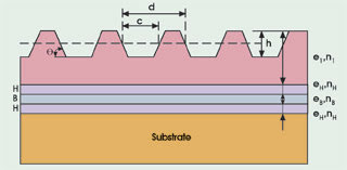
Figure 4. In this ion-etched multilayer dielectric grating, a multilayer dielectric mirror is deposited onto the substrate (H = high-refractive-index layer and B = low-refractive-index layer). The top layer may be thicker than the others and is ion-etched to produce the diffraction grating directly into the top layer.
For a configuration that is defined by groove density, wavelength and high- and low-refractive indices, the solution for the structure is finely determined by the thickness e1 of the upper layer (high or low index), the groove depth h (or h/d where d is the period) and the groove width c at half depth (or c/d). High efficiency is obtained for transverse electric polarization.
After manufacturing and initial testing of sample gratings, we selected gratings with a low-index upper layer for production of usable gratings inside a real laser compressor. Extensive damage threshold tests of sample gratings have been performed at LULI. These included small-laser-spot (100-μm focused beams), one-shot and statistical measurements. One-shot measurements yielded 2.5 J/cm2 in the femtosecond regime (in the right section of the beam).
A pair of such gratings was produced. The first pair had a density of 1740 grooves per millimeter; efficiency of 100 percent at 1056 nm; angle of incidence of 72.25°; 20 coating layers, with an SiO2 upper layer; and dimensions of 120 × 140 mm. The measured efficiencies were 98 percent (peak) and 96 percent (average) — near the 100 percent theoretical value. Wavefront quality was measured at λ/6, as expected (Figure 5). The pair of gratings was installed inside the laser compressor at the laboratory. The size of the beam was reduced from 90 to 18 mm.
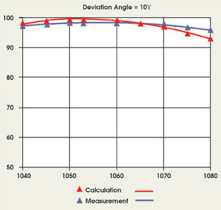
Figure 5. This graph depicts the theoretical and measured efficiency of a manufactured 120 × 140-mm dielectric grating.
The input energy is measured at the input of the compression chamber. A CCD camera images the surface of the second grating, where the intensity is the highest. The ratio between the maximum and the average fluence is 1.21 (beam profile).
A second-order autocorrelator measures the pulse duration at the output. The measured output energy allows researchers to determine the diffraction efficiency over the whole aperture of the laser beam. Inspection with a digital camera indicates microscopic damage of more than about 1 mm.
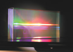
Figure 6. The 1740-grooves-per-millimeter multilayer dielectric grating with a blaze at 1.053 μm has a blank size of 210 × 420 mm.
We then manufactured a pair of 210 × 420-mm multilayer dielectric gratings that maintained an excellent efficiency uniformity (Figures 6 and 7). They were delivered to the laboratory to be used in a terawatt compressor to double the output power of the laser.
The angle of incidence was 72.5°, and the compressed pulse had a 275-fs duration. The overall diffraction efficiency was 85 percent; this means that, for each pass, the efficiency was as high as 96 percent. The damage threshold was above 1.7 J/cm2 at the 72.5° angle of incidence (or 0.51 J/cm2 on the surface of the gratings). Five shots at this fluence did not create any visible damage. The first viable damage occurred at more than 2.0 J/cm2.
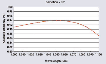
Figure 7. This map measures an average efficiency of 96 percent for a 210 3 420-mm multilayer dielectric grating.
We can now estimate the total benefit in output energy for a laser that has a dielectric grating compressor in comparison with a laser that has a classical gold-coated grating compressor. The gain in damage threshold in using the multilayer dielectric grating is 1.7 to 1 J/cm–2, which enables an increase by a factor of 1.7 in the input energy.
The gain in efficiency (fourth pass), which is 0.85 to 0.60, will also increase the output energy. Further damage tests on newly produced multilayer dielectric gratings have demonstrated an increase in the laser damage threshold of more than 2.5 times that of gold-coated gratings.
Future developments
Dielectric gratings present encouraging results in terms of efficiency and damage threshold. New petawatt-class laser centers in the US, Japan and France are looking for even larger grating areas. A new concept is to position two or more gratings in phase to constitute a mosaic of gratings.
A two-grating prototype was produced this year at the Laboratory for Laser Energetics at the University of Rochester in New York. When equipped with multilayer dielectric coatings, this type of grating may constitute the basis for very large gratings that can be used in pulse compressors.
Meet the authors
John R. Gilchrist is director of the custom optics group at Jobin Yvon Inc. in Edison, N.J. He obtained his doctorate in applied physics from the University of Strathclyde in Glasgow, UK.
Bruno Touzet is sales and marketing manager for the OEM and custom optics division of Jobin Yvon SAS in Longjumeau, France.