From finding first light to device characterization, a well-designed production system works swiftly and accurately.
Christiane Hummelt, Elektronik Laser System GmbH
Today’s telecommunications market requires reliable, low-cost transmitters and receivers. But for the mass deployment of optical connection technology, optical communications technologies must be cost-competitive with existing solutions. To achieve this, a cost-effective production of optoelectronic devices with maximum yield and throughput must be established. Unfortunately, most production and quality assurance processes do not yet meet these requirements.
What is often overlooked is the importance of the attachment of a single-mode fiber (or receptacle) to the transmitter or receiver. If the performance of this step is not satisfactory, time, money and resources are lost.
The five basic steps of an alignment and welding process for a standard single-mode device are: find first light, align the two parts for maximum coupling efficiency, spot weld to fix this position, perform gastight seam-welding and, in some cases, characterize the device (Figure 1). All this has to be done in well under 40 seconds, and the yield must be higher than 95 percent.
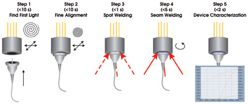
Figure 1. On a well-designed alignment and welding station, all five production steps take place in less than half a minute. Theintegration of traditionally separate production steps in one machine — such as seam welding and device characterization — reduces the investment costs and process times.
The transmitters and receivers in coaxial packages are contained in lensed housings. The counterpart to be fixed is either an optical fiber with a flange or a receptacle. This is the most basic approach of transmitter and receiver packages. More complex devices, such as bidirectional modules, combine sending and receiving in one package, but in principle, the same production steps apply.
Overcoming challenges
In a production system for aligning and attaching a single-mode fiber to a laser diode, difficulties are inherent in each step. But there are ways to overcome the challenges.
Step 1: Find first light. Load the housing and the flanged fiber into the alignment and welding machine. Then start the search routine to detect first light, which serves as the starting position for the alignment process.
Figure 2. Alignment stages with linear motors and glass scale encoders provide fast acceleration and excellent repeatability. The alignment algorithms are directly executed on the microprocessor of the motion control board. In this way, the exact position of maximum coupling efficiency is reached within seconds.
First, apply nominal current and measure the forward voltage to check whether the laser diode is functional. If the voltage is in the specified range, the process will start. Without this fast check, valuable time would be lost searching for nonexistent light in a defective part.
Strict mechanical tolerances and reference points on the parts reduce the search field to a minimum. A good balance between the costs of manufacturing the parts and the requirements of the alignment process must be found. Tolerances of 10 μm prove to be an economic compromise to fulfill both needs.
Based on the average starting positions of all the parts, the production machine teaches itself to find an optimum starting position from which to perform a spiral scan. It searches an area of 1 mm in diameter within several seconds.
To achieve such speed, the best approach is to run the alignment processes directly on the motion-control board of the alignment axes. The power signal is an analog signal that serves as feedback for the alignment routines. By using an analog input on the motion-control board, the power signal does not need to pass through additional interfaces. Positioning stages with linear motor and glass scale (for the position readout) provide high acceleration and speed, and excellent repeatability. This procedure takes about 10 seconds.
Step 2: High-resolution alignment. For the final alignment, move the two parts closer together and perform a high-resolution spiral scan to identify the position of maximum coupling efficiency. Depending on the beam profile, apply additional algorithms (such as geometrical center algorithms for flattop profiles). Use a glass scale as an encoder on the linear stages. With this encoder, a bidirectional repeatability with a deviation of less than 20 nm assures highest positioning accuracy. In combination with the sophisticated algorithms, the position of maximum coupling efficiency is found reliably. The high-resolution alignment should not take more than 15 seconds.
Step 3: Spot welding. After the position of maximum coupling efficiency is reached, move the two parts together so that they make mechanical contact. Spot welds fix them in that position in a fraction of a second.
This step is the most critical in the entire process. If postweld shift occurs, the position of maximum coupling efficiency is lost. The ratio of coupling efficiency is measured before and after welding. Tedious and time-consuming processes, such as laser hammering and bending, can attempt to realign the parts, but they are not always successful.
To avoid postweld shift, it is crucial that the contact plane between the two parts is as uniform as possible. One of the parts (typically the fiber with flange) is mounted to a half-sphere floating on an ultrathin air cushion. When the parts move together, the sphere tilts on two rotational axes until they are in full contact. Minimum force is used for this orientation because of the air cushion (Figure 3).
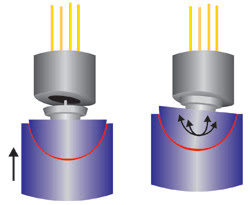
Figure 3. The key to reliable, fast packaging is an attachment procedure that is free of postweld shift. One part is mounted to a half-sphere that floats on an ultrathin air cushion. When the parts are moved together, the sphere orients itself against the counterpart on two rotational axes.
The weld spots also must hit the contact zone of the two parts exactly. The beams must be exactly balanced; i.e., each spot must have the same energy. All weld heads must have the same focal distance to the weld spots to provide the same diameter and the same energy per area. Three spots at an angle of 120° (which are welded simultaneously) provide the best weld geometry for coaxial parts (Figure 4).
Figure 4. A yield of more than 95 percent is reached when all welding parameters are optimized. For coaxial devices, three weld heads are orientedat an angle of 120°.
Optimizing all these factors fixes the parts without measurable postweld shift, maintaining the optimum coupling efficiency so that the part will meet or exceed performance criteria.
Step 4: Seam welding. After spot welding, one part is released from the gripper, while the other part is rotated around the optical axis to be seam welded. Because all weld heads are in the right focal position, no further movements are needed.
The speed of the seam-welding procedure is determined by several factors: the size of the device (i.e., the length of the seam), overlap of the weld spots, rotation speed of the axis and the laser’s pulse-repetition rate. The amount of energy coupled into the housing also has to be considered. Rotation speeds of 60° per second can be used for most devices.
The weld spots should overlap by more than 70 percent when the device needs to be gastight. In some processes, additional spot welds are used only to reinforce the connection between the parts. This is a restriction of current setups in which a gastight seam welding is either not possible or very complicated and time-consuming.
To check the quality of both the spot and seam welding, microsections through the weld spots are most appropriate (Figure 5). The area melted by the energy of the weld laser can be clearly identified. If there is a gap between the parts, the melted material will flow into it and warp the connection point. Also, the weld connection will be less deep and weaker, and if the gap is too large, no connection will be made at all.
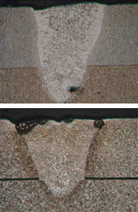
Figure 5. These microsections of spot welds with 100× magnification show a weld spot with a good connection between the two parts (top) and a gap between the parts (bottom). Melt material flows into the gap and warps the connection point.
This process takes approximately five seconds. In a well-designed production system, the fixation of the two parts with spot and seam welding is achieved in less than 10 seconds. The integration of the seam-welding procedure in the same machine reduces investment costs. Furthermore, when one considers the time needed for loading and unloading the parts on a second setup (plus alignment of the weld heads), integration of the two operations is clearly preferred.
Step 5: Characterization. Once the device is finished, electrical and optical performance can be immediately checked. To test a transmitter, switch on the diode laser and measure the transmitted optical power at the end of the optical fiber. Also monitor the forward voltage. A complete device characterization, including the measurement of the optical output power vs. current and voltage, the kink detection, the rollover current and the slope efficiency, takes less than two seconds. For a receiver, determine the sensitivity and the time response.
The machine’s thorough design allows the process time for the alignment and welding procedures to be cut well below 40 seconds. Traditionally, separate process steps, such as seam welding and device characterization, are performed in one system. There are two main advantages: no investment in additional machinery and no need for time-consuming device-handling between steps.
The key factor in increasing the yield is a welding process free of postweld shift. By avoiding this problem, the yield can be increased to more than 95 percent.
Meet the author
Christiane Hummelt is manager of the Mechatronics Div. at Elektronik Laser System GmbH in Gross-Zimmern, Germany.