Susan Snyder, Microscan Systems Inc.
The rising popularity of two-dimensional symbols for bar-code applications has increased the need for imager-based bar-code readers. In the past, the only solution for reading these symbols was complex vision systems designed for much more sophisticated tasks. Manufacturers wanted an imager that functioned like a laser bar-code scanner. The custom optics in a smart camera provide exactly that: the robust functionality of a fully contained vision system with the ease of use of a bar-code scanner.
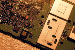
In this printed circuit board application, the custom optics in the smart camera provide the robust functionality of a fully contained vision system with the ease of use of a bar-code scanner.
Bar-code applications have a unique set of optical requirements. Off-the-shelf optics are not suitable because most commercial products are designed for digital photography. Standard optics take images similar to what the human eye sees. They have a large field of view, are used across the visible spectrum and are designed for use at relatively long distances.
For bar-code applications, the optics must have a small field of view and be close to the focal point because the object of interest is so small. For example, instead of photographing a sunset over the horizon several thousand feet away, the camera captures a data matrix symbol within 0.1 inch of square space on a component 5 inches away. Unlike digital photography, only the colors of the illumination system are relevant in bar-code applications. High-reliability illumination systems are LED-based and have a narrow spectrum compared with white-light illumination.
Directly marked symbols
Lighting plays an even more critical role in dynamic directly marked symbol applications. For example, smart cameras are commonly used in the automotive industry to read 2-D data matrix codes directly marked onto the metal substrates of car parts such as antilock-brake components. Smart cameras are installed at various points on the production line to read the codes on the parts as they travel through the manufacturing process.
Dot peen marking presents a challenge because it’s a percussive technique that uses changes in depth rather than color to create the light and dark elements of the data matrix symbol. As a result, lighting and the angle of lighting are critical. Because the cell fill is usually relatively small, grid mapping also is difficult, and the industrial environment often creates a high degree of image noise. Symbols etched into glass surfaces present a different lighting challenge. The highly reflective surface of glass causes variations in illumination to occur across the symbol, making it difficult to illuminate correctly.
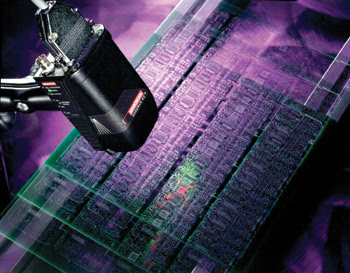
A two-dimensional data-matrix symbology is laser-etched onto a crystal oscillator component for work in process tracking.
To overcome these obstacles, Microscan Systems designed its smart camera Quadrus EZ with a patented internal and external LED ring and a specific amount of diffusion to provide even lighting on the symbol. By positioning the smart camera at the right angle of incidence, the symbol can be illuminated well enough for the image processing to decode it.
To meet the demands of dynamic applications, careful attention must be paid to every detail of image processing so that the highest possible speed and throughput can be achieved. It is not a problem to capture and process an object moving past a camera. The challenge lies in the ability to capture and process the next object.
Technology advances
Dramatic improvements in image-processing technology have made it easier to address these challenges. Memory and digital signal processing speeds continue to increase while the costs continue to drop because of reduced die sizes. Field-programmable gate arrays also have improved: Sizable internal dual-port memory and sophisticated clock management have been added, gate counts have increased, and speed capabilities are improving. As a result, some of the image processing that had previously been done with high-speed digital signal processors can now be off-loaded to the field-programmable gate array, which can perform these tasks in real time.
Additional consideration should be given to the CCD used to process the image. The primary types of CCDs used for bar-code applications are frame transfer and interline transfer. A frame-transfer CCD has a light-shielded storage area, separate from the imaging area. When integration is completed, the image is transferred into this area, one row at a time. The pixels in an interline-transfer CCD have a photodetecting region and a light-shielded storage area. When integration is completed, the signal collected in every pixel is transferred, all at once, into the light-shielded parallel CCD.
The advantage to using a frame-transfer CCD is that it maximizes the fill factor (effective pixel area) and provides a means for electronic shuttering. The disadvantage is that, because integration is still occurring during the image dump into the storage array, image “smear” may result. Image smear is not an issue with interline-transfer CCDs. However, the trade-off is in fill factor. Microscan opted for the frame-transfer CCD because it provides more fill factor for dynamic applications.
Field of view
In bar-code applications, depth of field is particularly important because it is directly related to ease of use. The larger the depth of field, the easier the smart camera is to set up. “When designing the optics for Quadrus EZ, it was important that it function as a laser scanner,” said Matt Allen, product marketing manager for Microscan. “This meant the user must be able to set it up in 30 seconds.” To set up Quadrus EZ, all the user needs to do is power it up, align the field-of-view locator to the 2-D symbol and push the button on the back to autocalibrate on the symbol. The user no longer has to manually adjust focal distances or play with exterior lighting to read tough 2-D symbols. Designing a flexible depth of field was instrumental in accomplishing ease of use. However, there is a trade-off.
Depth of field
Depth of field also minimizes the smart camera’s ability to collect light, which is important for dynamic bar-code applications. As a result, the depth of field must be optimized without decreasing the smart camera’s dynamic performance. The larger the depth of field, the smaller the f stop required and the less light collection achieved. To perform at high line speeds, the camera should operate at shutter speeds of 1/10,000 of a second, and the optics must be designed to allow enough light at this speed.
Two-dimensional codes are taking hold in several industries. As the popularity of direct part marking increases, so will the demand for more sophisticated lighting and optics combinations. Improved depth-of-field performance also will need to be developed. Before smart cameras can compete for ultrahigh-speed applications, more front-end hardware processing on the image is needed to provide real-time results.
Meet the author
Susan Snyder is market development manager for Microscan Systems Inc. in Renton, Wash.