It is crucial that all sides in a joint development and procurement program understand and document the scope of work, expectations and responsibilities of all parties.
Charles Synborski, Melles Griot Optics Group
When lens development programs go awry, the results often include blown schedules, ill-defined nonrecurring engineering programs, overpriced prototypes, rework and worse.
To avoid such problems, it helps to establish a seamless line of communications with the system or lens manufacturer early on. The focus should be on shared technical, schedule and budget realities. The entire process depends primarily on open, unambiguous and quantitative (written) communications. If it isn’t possible to clearly articulate the required system specification in terms that an optical engineering and manufacturing company can understand, it may not be the right time to begin the procurement process. Start with the basics.
Consider a typical example of a multielement compound lens application. If the object location in the generic compound lens or imaging application is near-field or at a distance of less than 10 times the focal length of the required optic (if this is known), the application more closely matches the case of a finite conjugate lens (Figure 1, top). Lenses of this configuration are most often encountered in image-forming applications; for instance, optical gauging and metrology systems, graphic arts and photographic instrumentation, and traditional finite conjugate microscopy.
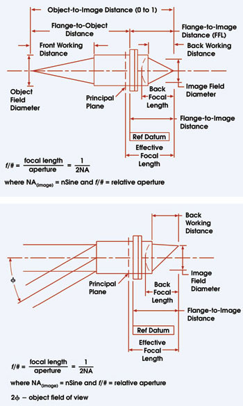
Figure 1. Typical “required” specifications will vary with the application, as shown for finite conjugate lenses (top) and infinite conjugate lenses (bottom).
Alternatively, if the object in the application is some distance from the imaging lens, or incident rays from the object are parallel to the optical axis (infinity qualifies as a distant location), the case is more like an infinite conjugate lens (Figure 1, bottom). These lenses are often applied to a wide range of laser micromachining and patterning applications common in the semiconductor and optical memory mastering markets.
The key to developing the specification is to focus on what the lens supplier will need to know about the application, or the instrument for which the lens is being developed; i.e., based on the instrument’s physical constraints, where are the object and image positions (the object-to-image distance)? What physical volume of space is available between the object and image for the lens designer to utilize?
If the available volume of space is oddly shaped or even folded, don’t worry. Define it. Also define the required in-plane size (diameter) of the object and the image fields (magnification); the space required between the image-side lens element’s outermost surface (its vertex) and the image location (back focal length); and the distance required between the lens’s barrel and the image position (back working distance).
Don’t forget the object side. How much space is available for the lens designer between the object location and the front edge of the lens’s barrel (front working distance)? Every lens must be fastened in some manner to the product or instrument it is designed to enable, so it will be necessary to determine the exact mechanical requirements or constraints surrounding the desired mounting method. For example, will the lens need to be replaceable in the field and aligned without sophisticated measurement tools? Is the optical axis of your entire system based upon the accuracy of the lens barrel and its mounting fiducials? The answers to these questions will have a profound impact on the lens barrel’s design and the test procedures that verify mechanical performance.
Geometrical optical characteristics of the lens, such as focal length, f number and numerical aperture, typically spring not from the above mechanical specifications, but from a company’s fundamental definition of success for the imaging system. What are the primary requirements for resolution performance (considering the characteristics of your light source)? How will that requirement be quantified and measured?
The resolution performance may be analyzed through spot-size measurements and specified at the 1/e2 intensity level or some similar metric. It may be characterized via the visual interpretation of the quality of imaged bar-targets or through determining the optical system’s modulation transfer function at application-specific spatial frequencies (typical in incoherent illumination scenarios).
It will be necessary to define how the desired imaging performance, resolution or modulation transfer function may vary over the entire image field, and over a range of focus positions along the optical axis. The image-resolving needs, coupled with mechanical constraints, will drive the focal length and lens aperture realities. Leave the determination of these data to the lens designers.
Trade-offs may be necessary because all image fields are not created alike. Some are not flat by design (common in certain graphic arts and photogrammetry lens applications). Because of the ever-present trade-off between cost and performance, it may be necessary to accept a design with a certain amount of residual image mapping or image placement error; i.e., image distortion, with the specific application dictating any allowable distortion.
Telecentric designs
Both the customer and the lens supplier must understand the degree of telecentricity required. In a purely nontelecentric world, the centroid of off-axis image points will walk off in a radial direction as a function of object or image plane defocus. Imaging systems embedded in optics-enabled manufacturing or in inspection systems often operate slightly out of perfect focus. Can that out-of-focus condition be allowed to induce errors in image placement within the image field? Not if the imaging system is attached to a highly accurate noncontact optical gauging system (or a weapon’s fire-control system).
Applications of this type require so-called telecentric designs in which the “chief ray” exits the lens parallel to the optical axis. The lens’s aperture stop is at the front focus, and its exit pupil is at infinity. In this design configuration, defocus may spread out or increase the size of the centroid of a point image — it will lose resolution — but will not change its position in the image field, which is a good thing. However, telecentricity not only costs money, but also increases lens diameter, taking up more valuable space. Use telecentricity wisely.
Source characteristics are as crucial to project success as any lens characteristic. Be prepared to discuss and specify the source type, center wavelength, bandwidth and power level for continuous-wave coherent sources, as well as peak and average energy levels, pulse duration and repetition rate, as appropriate (for pulsed coherent systems). If it is an incoherent emitter, know its source type, radiance, intensity vs. wavelength curve, size, shape and uniformity.
If bandpass or cutoff filters are to be employed, specify them and be prepared to explain why they are needed, because they have a big effect on imagery. Understand and document the characteristics of the image detecting or recording mechanism, be it film, photoresist (what type), a crystal, a discrete sensor, a linear sensor array or a two-dimensional sensor array. Key data include the spectral sensitivity and response linearity characteristics of the specific detecting/recording mechanism.
Next, consider required acceptance criteria. It is crucial that all sides in a joint development and procurement program understand and document the scope of work, expectations and responsibilities of all parties, schedule and definition of success, up front, in a well-thought-out written program specification. Both customer and supplier must understand how changes in scope will be requested by either party, estimated and approved for implementation during the development and post-development phases of the program.
Mechanical considerations
Earlier discussion touched on the role of the lens barrel design in helping to understand and define such system characteristics as front and back working distance, flange-to-object distance — if a finite conjugate configuration — and flange-to-image distance. That’s just the beginning of the story. The lens’s ultimate performance, stability, robustness and ease of use are intimately tied to its internal lens element mounting and positional adjustment strategies, and today’s marketplace has many mechanical strategies in play.
Internal lens elements may be “potted” in individual metal cells, including solid- and flexure-contact cell designs, using specialized adhesives. Individual optical elements also may be potted directly into mating features within the barrel. Lens elements and element-containing cells may sometimes be held with respect to mating metal features by retainers.
Sometimes the mechanical design must allow the technician to manipulate the centration of an internal lens element from outside the barrel during testing. Such mechanisms are commonly referred to as “pusher cells.” Some designs don’t allow the use of barrels at all. Instead, the optical-element-containing cells and air spacers are bonded in various ways to form a monolithic ready-to-use structure.
It is not uncommon for the accuracy of mechanical dimensions associated with metal cell and barrel structures to reach the level of perfection depicted by traditional optical tolerances. Modern manufacturing systems need to be employed to create high-tolerance lens barrels and internal mounting structures (Figure 2).

Figure 2. Producing lens components to tight tolerances most likely will require advanced manufacturing and testing processes, such as CNC turning centers for machining lens barrels (top left) and one-dimensional interferometers for certifying accuracy of machined cells and barrels (left).
Manufacturing and assembly
The mathematical lens design process is only the first step in achieving a successful lens development and manufacturing mission. Separating the mathematical lens design process from the remaining directly related and interdependent lens manufacturing, assembly and test processes adds risk to any development program.
The lens designer must optimize the optical design based on an intimate knowledge of the tools and capabilities of the manufacturing facility that will produce the finished product. He must know whether the manufacturer will use traditional pitch-polishing systems to fabricate the optical elements or whether advanced computer-numerical-control (CNC) tools will be applied. As tolerances shrink, the use of post-CNC phase measuring interferometry and magnetorheological finishing also may be required to produce and certify the lens element surface accuracy that is specified by the designer (Figure 3).
Just as the lens and mechanical designers control the choice of mechanical fabrication tools to be employed, the client’s optical efficiency or system transmission requirements strongly influence the design of the related antireflection thin-film coatings and their method of application.
The aforementioned lens element mounting and alignment mechanisms are often mixed within a design to meet specific technical requirements and to take advantage of cost-saving opportunities that arise. During assembly, each optical element in the stack that makes up a compound lens must be aligned precisely with respect to its neighbors so that its optical axis is collinear to a high degree with the lens system’s mechanical axis. That mechanical axis is, in turn, correlated to the instrument for which it was designed via its defined mounting fiducials. Experienced mechanical designers who are capable of working with tolerances in the submicron region are crucial members of the lens supplier’s staff.

Figure 3. Fizeau phase measuring interferometers may be required during postprocessing to certify that manufactured lenses meet designer specifications.
In many applications, the imaging performance requirements are so challenging that the tolerances on the homogeneity of optical materials used within the lens and the surface figure, thickness and optical centration needs of those elements are beyond what can be mass-produced for a reasonable price. In other words, if the lens maker toleranced the individual components that make up today’s high-performance lenses to achieve a 100 percent manufacturing yield factor, no one could afford to pay the price. Predicting the time required to deliver a finished lens would be nearly impossible.
To make life livable, lens makers have developed powerful in-process wavefront and geometrical aberration measurement techniques. In practice, the optical performance of an end user’s imaging system is characterized by proprietary interferometric instrumentation during testing and is mathematically modeled by the software tools originally employed to design the lens. Based upon measured data defining each system’s “aberration profile,” software tools recommend positional adjustments to internal components or recommend the use of alternate elements from inventory, to optimize performance and final test yield.
Today, such techniques predictably result in nearly 100 percent manufacturing yields for highly complex multielement lens systems at a reasonable price. Once again, the link among the optical designer, the software design tools, and the lens manufacturing and assembly methods is clear.
Every lens manufacturer has both generic and proprietary technology. The competitive edge may be an ability to hold tight tolerances while cost-effectively manufacturing thin optical elements. It may be a tightly held method of using specific optical shapes in the lens design that facilitates the use of lower-cost mounting. Maybe the company’s ability to hold mechanical tolerances is so advanced that its engineers can edge-mount elements in cases where their competitors must resort to more expensive, complicated and heavy potted cell designs.
Some design lenses so that every performance-critical internal optical element is adjustable from outside the barrel during final test. Others use phase measuring interferometry and deterministic machining methods to create a “corrector element” that is added to each lens to correct residual design and manufacturing-induced aberrations.
Regardless, lens designers must intimately understand the proprietary manufacturing, assembly and test methods of the manufacturers who will be tasked with making your lenses if they are to reduce cost while maximizing lens performance.
However, the advent of powerful, inexpensive and portable lens design programs has made it easy for a wide range of developers and consultants to design “paper” geometrical optical solutions that may seem to meet your optical imaging requirements. Without an intimate knowledge of the intended manufacturer’s proprietary mechanical design, element manufacturing, and system assembly and test methods, how can those disconnected PC-based consultants take advantage of the proprietary methods that allow most vertically integrated manufacturers to successfully deliver lenses on time and on budget? In most instances, such “disconnected optical design solutions” serve as little more than starting points for vertically integrated lens makers who, if allowed, will typically redesign the optical train from scratch, delivering a total solution.
Lastly, don’t be afraid to share information concerning the available nonrecurring engineering and recurring unit price budgets with the supplier candidates. They must make their own investment decisions as early in the process as possible, and their price proposal is dependent on accurate unit volume forecasts. Why would a buyer place the future success of an entire development and manufacturing program into the hands of someone who cannot be trusted with this information?
Conclusions
The process of understanding and specifying a custom-designed complex optical system or compound lens, selecting an appropriate supplier, and managing a successful concurrent engineering and Just-in-Time supply program has never been without risk. It seems like a complicated business, and if approached incorrectly, it can be. Fortunately, there are tried-and-true fundamental disciplines and process steps that, if respected, will help the savvy engineer, manager or businessman or -woman be successful.
Meet the author
Charles Synborski is director of marketing and sales at Melles Griot Optics Group in Rochester, N.Y. He has a degree in physics from Syracuse University, an MS in optical engineering from the Institute of Optics at the University of Rochester, and executive development certification from Babson College.