Software that includes scalar diffraction efficiency calculations for diffractive optical elements simplifies the design process and enables the creation of optimized optical systems.
David M. Hasenauer and Jay Wilson, Optical Research Associates
Diffractive optical elements offer the optical system designer powerful and often unique functionality in a compact package. For example, diffraction gratings can produce a large angular spread between closely spaced wavelengths, making them useful as dispersive elements in spectrometers and in wavelength division multiplexers (WDM). The performance characteristics of holographic optical elements, kinoforms and binary diffractives can be highly customized, permitting their use in applications ranging from correcting color aberration to beam shaping.
Performing optical design with diffractive optical elements has been challenging because it is difficult to precisely model certain aspects of their behavior. In particular, the amount of light that the component directs into each diffracted order — i.e., the scalar diffraction efficiency — typically must be computed separately and applied to the analysis results from commercial optical design software. Characterizing the scalar diffraction efficiency is important because stray light from unused orders can reduce contrast and modulation transfer function, and create ghost images.
Diffractive optics
This challenge has been addressed with software tools that compute scalar diffraction efficiency for several types of diffractive optical elements. This should enable the development of diffractive systems with improved performance and higher efficiency.
Most conventional optical systems operate by using refraction and/or reflection of light. Whenever a light ray encounters an interface between two materials that have different indices of refraction, part of the ray is refracted, and part is reflected. Snell’s law determines the angular relationship between the incident and refracted rays, and the law of reflection determines that of the reflected ray. The relative intensity of all rays is given by the Fresnel equations.
Diffraction is a consequence of the wave nature of light. The type of diffraction of concern here occurs whenever a light ray encounters a structure that is of a size on the order of the wavelength of the light. When this structure is repetitive, or periodic, the directions of the diffracted rays are given by Bragg’s law.
Unlike the simple cases of reflection and refraction, a diffractive surface can generate multiple beams, called orders. The relative intensities of the various diffracted beams depend upon the precise nature of the diffracting structure.
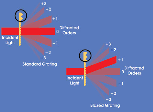
Figure 1. A diffractive surface can generate multiple beams, called orders. Blazing alters the characteristics of the diffractive element to put as much of the intensity as possible into a single diffracted order — in this case, the first order.
For example, Figure 1 shows the action of a simple transmission grating with a symmetric profile. In this case, most of the light goes in the undiffracted, or zeroth, order. The higher orders are arrayed symmetrically, and each positive and negative order of the same number is equal in intensity. It is possible to alter the profile — i.e., the groove angle and the shape — of the grating without changing its period, so that most of the light is directed into one specific order, such as the first. This is called blazing.
A variety of diffractive optical elements are in use, and several technologies are used to fabricate them. They typically are classified by the manufacturing methodology employed and/or function. Their classifications include surface and volume diffraction gratings, holographic optical elements, kinoforms, and stepped binary or multilevel diffractive optical elements.
Surface gratings feature grooves on their surfaces in a simple, periodic structure. To produce them, a master grating is created, either mechanically or by holographic etching. The former requires machining a pattern onto a glass substrate, and the latter involves exposing a photoresist-covered substrate to an interference pattern created with a laser.
Replicas are produced from the master using a variety of techniques, including embossing, molding and etching, depending on the required feature sizes; mechanical and environmental characteristics; performance; cost; and quantity. Diffraction gratings typically are used to disperse broadband light or to steer monochromatic beams. Common applications are in wavelength-separating systems such as spectrometers and WDMs.
Volume gratings, which consist of a periodic variation in refractive index inside a bulk material, are produced holographically. This is accomplished by exposing a thick layer of photosensitive material to an interference pattern created with a laser.
Computer-generated holograms can be made to perform beam shaping and steering, and other tasks. They usually are fabricated using lithographic and etching techniques similar to those employed for the manufacture of integrated circuits. However, the extremely complex masks for these diffractive elements are produced by a computer, rather than through the interference of laser beams.
A kinoform is a diffractive optical element commonly used to correct for dispersion and other aberrations caused by other parts of an optical system. One type of surface-relief kinoform is shown in Figure 2a. Unlike a grating, it is not a simple periodic structure. The way the kinoform is illustrated in the figure might cause it to be mistaken for the more familiar Fresnel lens. However, the scale of the features in the latter is macroscopic, so that it operates through refraction. In contrast, the kinoform’s features are small enough that it operates by diffraction.
Kinoforms are most commonly used in infrared systems. The long infrared wavelengths mean that the required feature sizes for kinoforms are large enough so that they can be fabricated directly onto the surface of conventional optical components using diamond turning. They also can be created on plastic elements by diamond turning of the mold insert.
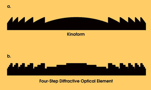
Figure 2. Cross sections of a typical kinoform (a) and the corresponding four-level diffractive optical element (b) illustrate how the former features smoothly varying analog functions and the latter, a series of discrete steps approximating the desired shape.
A binary or multilevel diffractive optical element is similar to a kinoform (Figure 2b). Although the surfaces of the kinoform are smoothly varying analog functions, the multilevel diffractive optical element approximates the desired shape only by breaking it down into a series of discrete steps. Because of their binary simplicity, multilevel diffractive optical elements can be produced by various etching and lithographic techniques.
Design solutions
In real-world applications, virtually all of these types of diffractive optical elements use blazing to deliver optimum system efficiency — that is, to put as much light as possible into the desired order. Scalar diffraction efficiency can approach 100 percent, but only for the nominal blaze design wavelength and for a specific angle of incidence. It falls off at other wavelengths and angles, with more of the incident light being directed into unwanted orders. This is perhaps the major design challenge in using diffractive optical elements.
Although many optical design software packages permit the use of diffractive optical elements, the ability to include the intensity effects of blazing in various analyses, such as modulation transfer and point spread function, has been limited. A typical assumption has been that 100 percent of the light goes into the blazed order. This has hindered the ability of designers to accurately analyze and optimize the performance of systems that incorporate diffractive optical elements.
The newest release of Code V, the optical design and analysis software package from Optical Research Associates of Pasadena, Calif., extends the way in which several common diffractive optical element types are defined to include parameters that determine the scalar diffraction efficiency for any given diffracted order. Code V can now be used to accurately determine scalar diffraction efficiency for kinoforms, stepped and sinusoidal surface gratings, and volume holographic gratings. Scalar diffraction efficiency results are automatically included in a number of the software’s analysis features, such as modulation transfer and point spread function. Moreover, and perhaps most importantly, the depth size of the grating structure can be made variable, allowing the efficiency to be optimized directly.
The positive impact of automatic scalar diffraction efficiency calculation can be gauged by reviewing two simple examples of systems that incorporate diffractive optical elements. The first is a visible-wavelength spectrometer operating in the Ebert-Fastie configuration, which features one large spherical mirror that the optical path hits twice and one planar reflective linear diffraction grating. The design relies on the use of a multilevel diffractive optical element as the grating. With this instrument, a major design goal was to determine the minimum number of levels required to achieve the desired efficiency for this component in the first diffracted order.
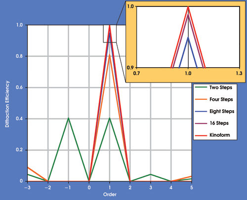
Figure 3. The diffraction efficiency was analyzed in each order for two-, four-, eight- and 16-step diffractive optical elements, plus a kinoform, all at 550 nm.
To illustrate the differences in scalar diffraction efficiency for different numbers of steps, the system was analyzed at 550 nm (Figure 3). For each multilevel diffractive optical element structure, the amount of light in each diffracted order was computed. An automated routine, called a macro, was used to collect these separate calculations and to plot them on a single graph. Analyses were performed using two-, four-, eight- and 16-level step (binary) gratings. A kinoform also was analyzed to provide a benchmark for ideal performance.
The blaze depth was optimized for the first order at a wavelength of 550 nm. The data showed that a 16-level step grating was the minimum necessary to approximate the performance of the kinoform, which yields 100 percent efficiency at the design order and wavelength. The designer could then use this data to set the grating design parameters based on the efficiency requirements of the application, together with any constraints related to cost and manufacturing limitations.
The next example is an air-spaced, germanium doublet lens with a kinoform that is turned by diamond point on the back surface of the first lens. The lens is intended to operate over the 8- to 12-μm wavelength band, and it could be used as the objective in a night-vision or forward-looking IR system. The goal was to achieve good color correction, modulation transfer function and maximum efficiency (overall throughput) over the operating range, while minimizing system weight, size and cost.
Without the kinoform, this lens has approximately 0.8λ of axial color aberration. The addition of the kinoform reduces this to approximately 0.1λ.
In terms of maximizing efficiency, it would be natural to set the blaze depth — i.e., the physical groove depth — for the kinoform to provide maximum efficiency at 10 μm, the center wavelength of its intended operating range. However, because the efficiency does not drop off symmetrically with wavelength, the performance on the short-wavelength side suffers.
The software was used to automatically optimize the blaze depth, given the target of achieving equal efficiency at both ends of the transmission spectrum. It determined that an optimum blaze depth for a wavelength of about 9.6 μm delivers peak overall system efficiency (Figure 4).
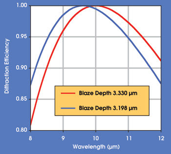
Figure 4. The diffraction efficiency vs. wavelength is shown for the germanium doublet lens for a blaze depth centered on the wavelength transmission band, and after optimization to achieve equal values at either end of the transmission spectrum.
Scalar diffraction efficiency calculations also were used to determine how ghost images from the diffracted orders outside the design order affect system modulation transfer function (Figure 5). Code V was used to compute the modulation transfer function by incoherently combining point spread function data from the design order and the next ±2 orders and performing a fast Fourier transform. The resulting plot shows an appreciable drop in modulation transfer function because of the diffraction ghosting effects — especially on-axis, where the design order performance is essentially diffraction-limited. Thus, failure to include the contributions of these other orders would lead to an overly optimistic estimate of final system performance.
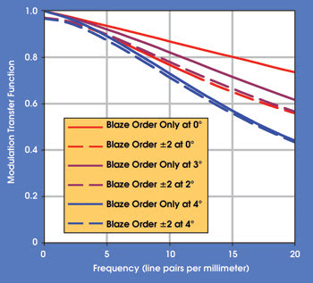
Figure 5. The modulation transfer function of the germanium doublet considered the light in the blaze order as well as in the blaze order and the next ±2 orders.
The use of diffractive optical elements enables optical designers to produce systems with unique performance and to achieve otherwise unattainable targets for system size, weight or cost. The advent of software that automatically includes scalar diffraction efficiency calculations for diffractive optical elements will both simplify the design process and enable the creation of more highly optimized systems.
Meet the authors
David M. Hasenauer (e-mail: [email protected]) is Code V product manager, and Jay Wilson (e-mail: [email protected]) is Code V sales engineer at Optical Research Associates in Pasadena, Calif.