For more than three centuries, the Earth’s atmosphere has frustrated astronomers. The layer of gases that we breathe also distorts the images formed by telescopes. This means that conventional telescopes of more than a few centimeters in diameter cannot reach the resolution limit set by their optics.
Tom Gonsiorowski, Adaptive Optics Associates, Inc., a Wholly Owned Subsidiary of Northrop Grumman Systems
To Isaac Newton the problem was clear, and in 1704 he realized the effects of atmospheric turbulence on image formation. Just as heat waves shimmering above a hot patch of ground can distort our view, the image of a distant object formed by a telescope is distorted by the temperature variations in the intervening atmosphere. Therefore, light entering the telescope is traveling in slightly different directions at different places on the entrance aperture.
The image size and quality depends on a statistical measure of the spatial frequency of the turbulence called the coherence length, or r0, typically about 10 cm at a good site. Hence, even at a good site, the resolution of a big telescope, 4 or 8 m in diameter, will be similar to that of a 10-cm-diameter telescope; the image will never get any sharper than the atmosphere allows. With atmospheric turbulence, it is as if the big single aperture of a telescope were replaced by an array of small telescopes of aperture r0, with each telescope jiggling independently of all the others, so that all the separate point images almost never coincide. The rate at which the telescopes are jiggling is given by another statistical parameter called the coherence time, usually on the order of one millisecond. So the image is blurred by tremors only a hand’s width in size, whose motions are varying a thousand times a second.
A far-out proposal
One remedy that Newton proposed was to get as far above the atmosphere as possible. This is why modern astronomical telescopes are built on mountain peaks, flown on balloons and aircraft, or, like the Hubble Space Telescope, placed in orbit around the Earth.
Because the Space Telescope is outside the atmosphere, it realizes the full resolution of its 2.4-m aperture and has yielded revolutionary results in astrophysics. Still, it is only one telescope and observations can be done only at a limited rate. It is also much smaller than the new generation of 8- and 10-m class telescopes like the Keck I and II, Gemini, the Very Large Telescope (VLT) and Subaru. Thirty years ago astronomers could only dream of such telescopes, but today there are at least 10 in use and even larger 30-m class telescopes are under construction. Realizing the full resolution of such large apertures will provide major advances in the science of astronomy.
Fortunately, the technology exists to make this possible.
In 1953, Horace Babcock proposed an instrument that would measure the atmospheric distortions in real time and correct them using a fast, refigurable optical component1. Although the technology available then was not adequate to the task, the basic concepts, supported by contemporary technologies, have finally evolved into the current field of adaptive optics.
Fixing the image
A large number of adaptive optics (AO) systems are in use in both the defense and the astronomical communities. They are generally of the form shown in Figure 1. A large reflective telescope is imaging a distant point-like object above the atmosphere. Although the light arriving at the telescope should be nearly a plane wave, it is instead highly distorted by passage through many localized air masses of varying temperatures (and varying indices of refraction).
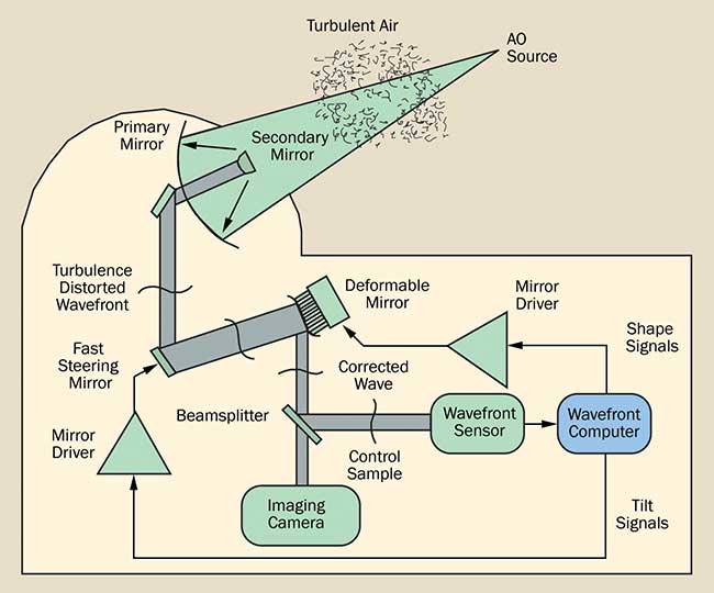 Figure 1. Schematic of an adaptive optics system.
This aberrated wavefront is divided using a beamsplitter and sent to the main imaging camera (or other detection instrument such as an imaging spectrometer) and a wavefront sensor that controls a device to correct the wavefront phase. The wavefront sensor optically analyzes the beam sample and generates signals that are used by a very high-speed processor to compute estimates of both the overall wavefront jitter, or tilt, and of the higher-order wavefront shape. These signals are then used to form an optical feedback loop that tries to keep the incoming beam flat, yielding a corrected, high-resolution image in the camera/sensor focal plane. The tilt signals drive a fast-steering mirror to hold the object in the center of the image field; the shape signals are applied to an advanced component called a deformable mirror.
The deformable mirror is often a glass face sheet bonded to a two-dimensional array of piezoelectric transducers or, as in the bimorph mirror, a continuous bimorph structure of glass and piezoelectric material. Micromachining technology can also be used to produce membrane mirrors with electrostatic actuators. These devices are not as robust as their glass counterparts, but they are significantly less expensive and have the possibility of being mass-produced. In all these mirrors, the transducers deform the face sheet so that it exactly cancels the atmospheric distortion. Another type of phase-controlling device uses an array of liquid crystals with a refractive index that can be controlled by an applied voltage. However, these devices are generally too slow for atmospheric adaptive optics and their spectral transmission is limited.
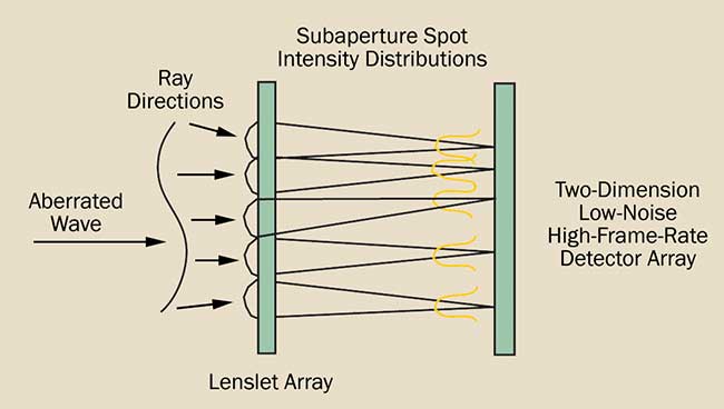 Figure 2. Operating principle of a Shack-Hartmann wavefront sensor.
Another key component of the AO system is the wavefront sensor. Many types have been developed and a typical approach, the Hartmann sensor, is shown schematically in Figure 2. The Hartmann sensor is derived from the classical technique for measuring telescope primaries. The aberrated wave enters from the left. The wavefront curvature means that localized parts of the beam are traveling in slightly different directions at different places, as shown by the ray arrows (Newton’s Rays of Light). These rays strike an array of lenslets whose diameter is chosen to match the dimension r0 at the telescope primary. The lenslets break up the main aperture into subapertures, and behind each subaperture a focal spot forms. The local ray direction determines the position of each subaperture’s focal spot and a detector array is used to measure these spot locations. From the spot positions, the shape (and tilt) of the input beam can be calculated and used to correct the beam.
However, as the atmosphere randomly perturbs the wavefront phase, how can we know the correct wavefront? The AO system, and specifically the wavefront reconstructor, requires a calibration source outside the atmosphere with known initial phase to determine the effect of the atmosphere on the wavefront. A nearby star could be used, but these are generally too faint and cannot be used if the object to be imaged is moving.
Solving the source problem
Babcock pointed out that an adaptive optics system needs a fairly bright source to operate effectively, which limited the range of astronomical objects that could be profitably studied. This remained a significant difficulty until 1981, when Julius Feinleib of Adaptive Optics Associates Inc. (AOA) proposed creating a source artificially by projecting a high-power laser in the desired direction and utilizing the molecular backscatter from the high-altitude portions of the beam to drive the AO system2. An example of a laser guide star is shown in Figure 3.
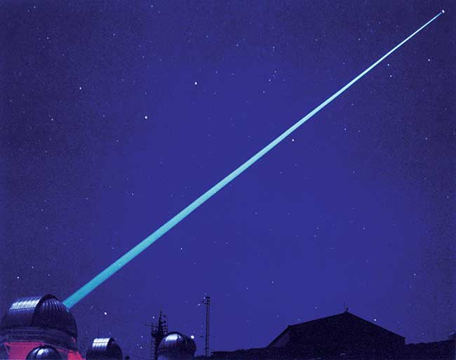 Figure 3. A laser guide star in operation at Starfire Optical Range.
Feinleib’s idea was immediately classified and thereafter developed secretly by the defense community. In 1985, it was independently proposed in the open literature by Foy and Labeyrie3. Ultimately, the defense work was declassified and the technique has come to be known as the laser-guide-star approach, which has vastly expanded the utility of adaptive optics and is an area of much research. In 1993, Babcock and Feinleib were awarded the Rank Prize for their contributions to adaptive optics.
State of the art
Advances in electronic imaging and computing power have now made it possible to implement the Hartmann approach to wavefront sensing in a small, table-top package; manufacturers include AOA, Lumetrics Inc., CILAS in France, and several others. By including some simple electronic boards in the system’s computer, the device can also control deformable mirrors made by AOA-Xinetics, OKO Technologies, CILAS, and Boston Micro-Machines. With the increase in computing speed it is now even possible to perform all the calculations for atmospheric adaptive optics with Pentium processors, freeing adaptive optics systems from the need for dedicated signal processing cards. This use of standard components to make an adaptive optics system shows that the technologies are reaching maturity.
AO systems are in use and under continuing development at a large number of locations worldwide. Pioneering work was performed at the U.S. Air Force’s Phillips Laboratory, which has released diffraction-limited, laser-guide-star-driven results for visible wavelengths using a meter-class telescope. Raytheon has delivered the AEOS (Advanced Electro-Optical System) to the Phillips Laboratory’s site on Mt. Haleakala, Hawaii. The system is used on a 3.67-m telescope and has a 941-actuator deformable mirror.
There are also many adaptive optics systems in use for astronomy. Practically all of the new, 8-m class telescopes have adaptive optics and AO systems are being retrofitted to many 4-m class instruments. Examples of systems in regular use for astronomical research include the Very Large Telescope of the European Southern Observatory (http://www.eso.org/sci/facilities/develop/ao.html) and the Keck I and II telescopes of the W. M. Keck Observatory (https://www2.keck.hawaii.edu/optics/lgsao/lgsbasics.html). Figure 4 shows the ALFA4 system built by AOA for the Max Planck Institute for Astronomy’s Calar Alto Telescope. The ALFA AO system utilizes a laser guide star; a fast, sensitive camera that captures 1000 fps; and a 97-actuator deformable mirror.
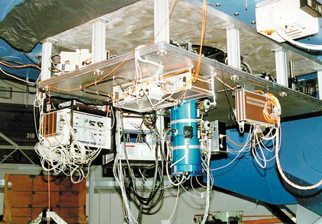 Figure 4. The ALFA System installed on the Max Planck Institute for Astronomy’s telescope in Calar-Alto, Spain.
The success of these AO systems has helped to spur construction of even larger 30-m class telescopes including the European Extremely Large Telescope in Chile and the Thirty Meter Telescope in Hawaii. These telescopes will require multi-conjugate and multi-beacon adaptive optical systems, where the turbulence of different atmospheric layers is measured with separate laser beacons using multiple wavefront sensors.
Not just for astronomy
Adaptive optics is finding many new applications outside defense and astronomy. Wavefront sensors are also being used in optical testing and manufacturing. The shape of optical components can be measured as they are manufactured. Applications range from the measurement of telescope mirror figure to the control of the alignment of coupling lenses to the optical fibers used in telecommunications. A particularly successful use of a wavefront sensor for optical testing is on the Hubble Space Telescope repair mission, which was aided by an ultrahigh-accuracy wavefront sensor built by AOA. The sensor, called the Aberrated Beam Analyzer (ABA), was used to test the Corrective Optics Space Telescope Axial Replacement (COSTAR) and Wide Field/Planetary Camera (WF PC) II systems prior to launch for the Hubble Repair Mission. The sensor uses an advanced variant of the Hartmann technique to achieve absolute accuracies of better than λ/100 rms, and long-term repeatability as high as λ/2000 rms4. It was so successful that the instrument has become the benchmark for testing all Hubble Space Telescope Instruments.
In the medical field, retinal photography can be improved by compensation for the turbulence induced by intraocular fluid circulation,5 and eye surgeons can use a wavefront sensor to measure the shape of a patient’s cornea during procedures like laser keratectomy. In ophthalmology, both Visx and Zeiss Humphrey have developed Hartmann sensor-based instruments to measure the optical prescription of a patient’s eye. Adaptive optics is also being used in microscopy6 to overcome spatial variations in the refractive index of the specimen that compromise image quality — a particular problem when imaging deep into thick biological specimens.
Conclusion
Adaptive optics, once only an astronomer’s dream, is now a mature technology being employed in many disciplines including medicine and the manufacture of consumer items, while the defense and astronomy communities continue to develop bigger and faster systems.
The component technologies required for adaptive optics are also having an impact far outside the field. High-speed machine-vision cameras are now commercially available, supported by real-time processing needed for fast, automated inspection, and control. Many consumer cameras have electronic image stabilization, and the micro-optics technologies originally developed for Hartmann sensing are creating applications in laser diode array control, conditioned light generation and advanced displays.
AO systems demand detectors with high quantum efficiency, noise levels below 100 electrons per pixel, and speeds of thousands of frames per second. Computation rates in excess of 10 billion operations per second sustained are in current use, and deformable mirrors having hundreds of actuators are in service. Until recently, these systems have cost millions of dollars per installation, but the commercialization of fast computers and cameras is reducing this cost dramatically. As technology advances, adaptive optics will continue to find new applications.
References
1. Babcock, H. W., The possibility of compensating atmospheric seeing, PUBL. ASTR. SOC. PACIFIC (1953), 65:229-236.
2. Collins, G. P., Making stars to see stars: DOD adaptive optics work is declassified, PHYSICS TODAY (1992), 18.
3. Foy, R. and A. Labeyrie (1985). Feasibility of adaptive optic telescope with laserprobe. ASTRON. ASTROPHYS. 152:29-31.
4. Bruno, T. L., A. Wirth and A.J. Jankevics (1993). Applying Hartmann wavefront-sensing technology to precision optical testing of the Hubble Space Telescope correctors. Proc. of the SPIE. 1920:328:336.
5. Roorda, A. and Williams, D. R., Adaptive Optics and Retinal Imaging, Vision Science and its Applications, OSA TECHNICAL DIGEST (Optical Society of America, 2000), paper NW5.
6. Booth, M. J., Adaptive optics in microscopy, PHIL. TRANS. R. SOC. A (2007) 365, 2829–2843.
Agreement
Copyright © 2017 by Adaptive Optics Associates Inc. Published by Laurin Publishing Co. Inc. with permission.