Fast applications require fast imaging.
Hiromasa Maruno, Shimadzu Corp., and John A. Monti, Shimadzu Scientific Instruments
High-speed video cameras can visualize high-speed phenomena that the naked eye cannot see. Although earlier versions used film, new types use a videotape recorder and solid-state imaging, enabling applications for high-speed photography in a number of fields.
Recent advances in PCs and peripheral digital technologies are enabling mainstream high-speed video cameras to contain solid-state-imaging technology that handles images as digital signals. To meet today’s ever-expanding scope and range of high-speed applications, cameras must photograph even faster phenomena.
Academic institutions, manufacturing industries and government agencies must image high-speed phenomena. Researchers, developers and engineers use these images to clarify an object’s behavior and to make discoveries and interpretations.
High-speed requirements
For high-speed imaging to be useful, not only must it be fast, but it also must achieve low noise and be operable under low-light conditions. An in situ image storage system (ISIS) CCD image sensor, such as the one manufactured by Shimadzu Corp. and used in the HPV-1 camera, can help with the low-noise requirement. It stores image data internally and, during the image capturing phase, the electrons generated at each photogate are simultaneously transferred to and stored in the linear CCD storage. The CCD cells are aligned so that the distance of the charge transfer is shortened. In this way, transfer speed increases without losing much of the transfer efficiency. Subsequently, noise decreases.
To achieve optimum use of the chip, the linear CCD storage are tilted about 4° against the grid axes of the photogate. Each linear storage can store 103 consecutive signals. Because the readout vertical CCD is part of the linear CCD storage (i.e., it is located at the bottom and consists of 12 CCD cells), the ratio of the area occupied by CCD cells can be decreased; therefore, the large size of the photogate can be used.
Path switched
The trapezoidal CCD cell at the confluence of the readout vertical CCD and the adjacent linear CCD storage functions as a switch that controls the path of change transfer. The path can be straight along the linear CCD storage to the bottom or from the upper readout vertical CCD to the adjacent lower readout vertical CCD.
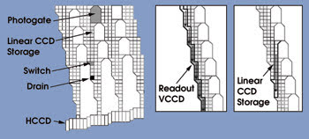
Figure 1. A vertical drainage is set for overwriting in the readout vertical CCD (i.e., the bottom of the linear CCD storage).
A vertical drainage is set for overwriting in the readout vertical CCD (i.e., the bottom of the linear CCD storage) (Figure 1). During image capture, the electrons generated at the photogates are transferred to the linear CCD storage one after another, and the electrons move from one CCD cell to the next. The electrons that have reached the bottom of the linear CCD storage are then drained out. In this way, the latest 103 images are stored in the linear CCD storage at any time.
When the trigger signal is sent, the transfer stops after any frame, which can be set as one of the control parameters. If the transfer stops immediately after the trigger, for example, 103 images taken before the trigger remain in the linear CCD storage. If the transfer stops 73 frames after the trigger, 30 images before and 73 images after the trigger are in the storage. Such a flexible trigger enables users to take pictures at the moment of interest.
After stopping the image capture, the image signals are read out via cooperation of the linear CCD storage and the readout vertical CCD.
Because the ISIS-CCD photodiode area is ~580 mm2 — six to 60 times greater than a conventional CCD (10 to 100 μm2) — it is possible to perform high-speed photography under relatively dim illumination. This enables researchers to use the camera without additional lighting in the area, eliminating a possible expense or the need to reconfigure a laboratory area.
High-speed imaging can benefit a variety of fields, such as natural phenomena, explosions, combustion, high-speed fluid flows, high-velocity projectiles, aerodynamics, electrical discharges and destructive phenomena.
In sensors without image storage capacity, the maximum frame rate is determined according to the amount of time required for all of the image information to be read out. When extremely high frame rates are used with such a sensor, the only way to transmit information commensurate with the frame rate is to reduce the total amount of information transmitted; i.e., to reduce the resolution of the image(s).
Thus, these types of high-speed cameras trade off increased recording speeds for reduced resolution. The HPV-1, however, suffers from no such drop-off in resolution, making it effective for photographing phenomena that demand both high speed and high resolution.
Precisely observing what happens when a bullet explodes into an object or when an explosive is detonated, or determining the exact moment a part breaks in materials failure testing, can aid researchers in identifying crucial parts of evidence or in developing better, safer products.
Catching rapid events
Researchers image shock waves after an explosion to determine the causes of destructive phenomena and to discover countermeasures. Imaging also can be used to visualize conditions simulating spacecraft re-entry. Spacecraft traveling at extremely high speeds (almost 6 km/s) are subjected to shock waves upon re-entry into the Earth’s atmosphere, and the aerospace industry uses such imaging when performing research on fuselage design.
The propagation and reflection of a shock wave was photographed by Tohoku University’s Institute of Fluid Science in Sendai, Japan. A microexplosive charge loaded in the test chamber was ignited by a pulsed laser to generate a shock wave that propagated through the air at the rate of 400 m/s.
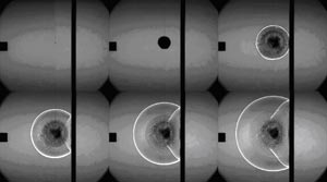
Figure 2. The propagation and reflection of a shock wave was taken at a rate of 500,000 fps. Images courtesy of Tohoku University’s Institute of Fluid Science.
Shock waves are not normally visible but can be seen using a special Schlieren optical system. The shock wave was recorded at 500,000 fps (Figure 2). The entire chamber can be observed, showing the shock wave propagating through the air and reflecting off the reflection plate. At 1 million frames per second at increased magnification, the ripples in the reflected wave can be clearly seen (Figure 3).

Figure 3. This propagation and reflection of a shock wave was taken at a rate of 1 million fps.
Although the shock wave details of large explosions such as nuclear blasts can be monitored effectively by cameras recording at a few hundred frames per second, obtaining comparably sharp, detailed images of smaller explosive events requires that the camera frame rate also be increased. It has been estimated that a tenfold increase in frame rate is required for a threefold decrease in the magnitude of the explosion. Recording the details of shock waves from microscale explosions requires frame rates of 250,000 to 1 million fps. The high-speed camera can attain such recording speeds and enables more experimentation at smaller scales and at greater cost efficiency.
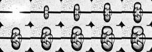
Figure 4. This image of ignition and combustion propagation in an internal combustion engine was taken at a rate of 10,000 fps. Images courtesy of Ashikaga Institute of Technology.
Images of ignition and combustion propagation in an internal combustion engine reveal the initial stages and propagation of combustion and are used to research engine function and performance.
Researchers at Ashikaga Institute of Technology in Japan took images in a test chamber filled with propane gas that was ignited by a spark across two electrodes.
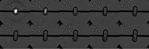
Figure 5. This image of ignition and combustion propagation in an internal combustion engine was taken at a rate of 100,000 fps.
Images taken at various recording speeds show that different recording speeds reveal different details of the same phenomenon. For example, a low recording speed clearly shows the overall combustion propagation (Figure 4). Increasing the speed allows observation of the very initial stages of combustion propagation (Figure 5). Further increasing the speed reveals the generation of a shock wave, which then propagates in a ring pattern (Figure 6). Such detailed information is important in determining the force distribution during the combustion event.
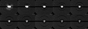
Figure 6. This image of ignition and combustion propagation in an internal combustion engine was taken at a rate of 1 million fps. Courtesy of Ashikaga Institute of Technology.
The high-speed imaging of ink droplet status is conducted to learn more about printer head operating conditions. Other than trial and error, the only way to investigate variables involved in the performance of ink-jet printers is to directly observe the process of droplet formation, ejection from the print head and deposition. The ability to visually follow the entire process allows for more efficient testing, monitoring and quality control.
In a test, a 40× magnification optical system was used to record images of ink droplets as they were injected from the nozzles. The light from a single-flash strobe was transmitted through an optical fiber to the printer nozzles, near the ink droplets. The ink-droplet-injection start signal (switch) provided the trigger signal. A waveform generator adjusted the timing of the ink-droplet injection with the start of the strobe illumination.
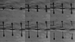
Figure 7. These images of ink droplets injected from nozzles were taken at 12-μs intervals after the start of ink injection (rate: 250,000 fps).
Images of the injection of ink droplets from nozzles were recorded at a rate of 250,000 fps (Figure 7) and show that ink droplets are not spherical and that droplet tails remain attached, rather than breaking away.
Similarly, injection of ink droplets from nozzles was imaged (Figure 8), but under different operating conditions so that the tails seen in Figure 7 broke away, resulting in a clean, spherical shape. If the droplets emerged from the print head as spheres and were deposited on the surface of the print medium at the correct rate, a clean, crisp copy was obtained. However, if there was tailing of the droplet, too much or too little mass of ink injected (drop diameter), improper frequency of drop deposition, or fouling or clogging of the print head, an unacceptable copy resulted. The HPV-1 allows detailed monitoring of this process.
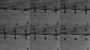
Figure 8. The images show ink droplets injected from nozzles (rate: 250,000 fps).
Although droplets appear to fly both upward and downward in these images, the upper droplets are actually phantom images on the ink-head surface.
Biomedical imaging
Engineering and materials science applications for high-speed digital photography such as those described above are usually well developed. However, ultrahigh-speed digital imaging also is finding use in biomedical fields. For example, Yuuske Miyake, Shiniji Deguchi and Seiichi Washio of Okayama University in Japan recently reported on using high-speed imaging with the HPV-1 for measuring pressure and deformation during oscillation in a vocal cord flow path model. This work was presented in January at the 18th Bioengineering Conference of the Japan Society of Mechanical Engineers, Bioengineering Div. Although their work involved a model system, real-time videostroboscopy of vocal cord motion is used in clinical practice as well as in research.
Perhaps one of the most exciting applications for high-speed imaging is the possibility of increasing the spatiotemporal resolution of action potentials in cardiac and nervous tissue. For example, some researchers are optically recording action potentials with second-harmonic-generation microscopy. A fast system could yield optical images of subcomponents of the action potential such as pre- and post-threshold.
Meet the authors
Hiromasa Maruno is an applications scientist with the Research & Development Group, business development department, Analytical & Measuring Instruments Div. of Shimadzu Corp. in Kyoto, Japan.
John A. Monti is senior scientist at Shimadzu Scientific Instruments in Columbia, Md.; e-mail: [email protected].