Photonic method can be many times more accurate than conventional one.
Hank Hogan
The clearance between a turbine blade and its housing is critical to the machine’s performance. Too large a spacing results in detrimental leakages, but contact between the blade and housing could destroy the machine. Because the spacing varies with temperature and pressure during operation, optimal performance requires real-time monitoring of the clearance.
In industrial practice today, most turbines rely on inductive or capacitive sensors to measure the ~500-μm clearance between the blade tip and the housing. These sensors, however, have a limited accuracy (of about 50 μm) and do not function with newer plastic or ceramic turbine blades. As an alternative, researchers at Technische Universität Dresden in Germany have developed an optical technique that avoids these pitfalls of conventional measurements.
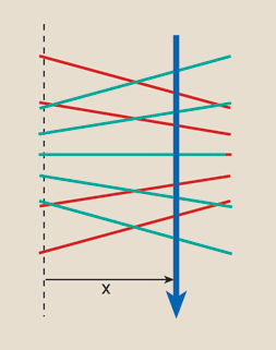
Figure 1. The investigators create two fanlike fringe patterns at two wavelengths (represented here by red and green lines), one converging and the other diverging. An object passing through the patterns (blue arrow) scatters light each time it passes through one of the fringes. Knowing the geometry of the fringe patterns, the researchers measure the frequency of light scattered at both wavelengths. From these data, they calculate the location (X) of the object.
The approach creates two interferometric fringe patterns in the space between the blade tip and the housing (Figure 1). Moving through these patterns, the blade tip scatters light from each fringe, and the investigators calculate the distance between the blade and housing from the frequency of scattered light (see caption of Figure 1 for a full explanation). Doing the arithmetic, it turns out that the distance is simply proportional to the ratio of the frequencies scattered from the two fringe patterns.
To create the patterns, the scientists designed a compact fiber optic probe (Figure 2). They mounted a 200 × 82 × 54-mm measurement head on a water-cooled base because the machine reaches a temperature of 280 °C. The measurement head illuminated a small volume between the tip of the turbine blade and the housing through an 8-mm-diameter, 6-mm-thick window whose inner surface was flush with the housing surface.
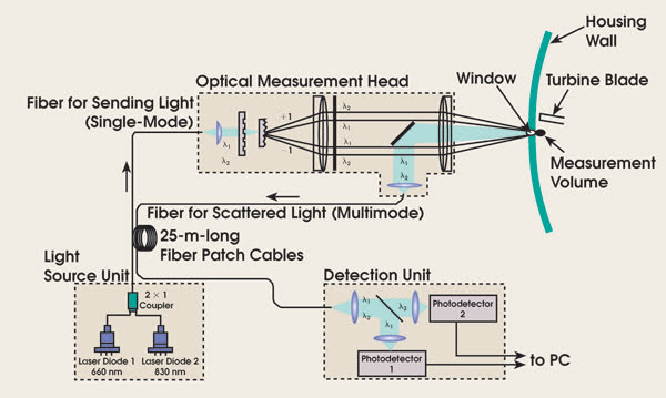
Figure 2. The measurement system comprised three packages: the source of dual-wavelength light, the measurement head mounted on the machine and the detection unit. ©OSA.
To test the system, the investigators performed experimental measurements on a transonic centrifugal compressor test rig running at a maximum speed of 50,000 rpm (833 Hz). The machine has 26 blades, so the frequency of the scattered light was approximately 21,658 Hz. The speed of the blade tips at the measurement location was 586 m/s.
The researchers were concerned that the window might become contaminated during operation, but there was no sign of this in the experiments.
They collected data using both the optical and a conventional capacitive technique during a period when the blade tip to housing distance was changing because of a throttle change (Figure 3). The optical technique measures only relative displacement, so they used a capacitive measurement to calibrate the first optical measurement.
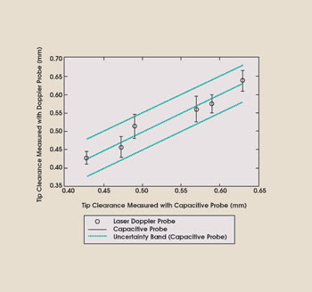
Figure 3. The experimental data indicated that the uncertainty of the optical approach (~20 μm) is better than that of the conventional capacitive one. Moreover, the investigators believe that design improvements could reduce the uncertainty of the optical measurement to ~1 μm. ©OSA.
In practice, the initial distance between that of the blade and that of the housing would have to be calibrated separately.
Figure 3 shows the uncertainty of both the optical and the capacitive measurement; the former is approximately half the latter. In absolute numbers, the investigators estimate that the uncertainty of the optical technique is about 20 μm. And they believe that, with readily achievable design improvements, the uncertainty could be reduced to 1 μm.
Optics Letters, May 1, 2006, pp. 1217-1219.