High-order modes may be the key to even higher powers from diffraction-limited fiber lasers.
Siddharth Ramachandran, Samir Ghalmi and Man F. Yan, OFS Laboratories
In the past few years, ytterbium-doped fiber lasers have achieved diffraction-limited outputs at multiple kilowatt levels, and they now compete with or surpass their more complex counterparts: bulk, solid-state lasers. An all-fiber approach offers two key advantages over bulk lasers — long interaction lengths and the prospect of building robust reliable systems by splicing disparate components, obviating the need for free-space alignment and optics.
The long interaction length enables distributed thermal management as well as high single-pass gain, thus offering the possibility of higher power levels than those achieved by solid-state lasers.1 In addition, fibers offer the possibility of dispersive design, which would be beneficial for ultrashort-pulse (pico- to femtosecond) systems.
The drive toward increasingly higher-power fiber lasers has been enabled primarily by the availability of high-brightness semiconductor pump lasers but is now limited by nonlinearities resulting from high intensities in fibers. Hence, recent development efforts have focused on large-mode-area fibers in which intensities are lowered, and fibers with effective mode areas as large as 300 μm2 are now commercially available.
However, when scaling to even larger areas, the signal becomes increasingly unstable (lossy and susceptible to division of energy into other modes) as the modal area of the fiber increases.2 As an alternative, we have demonstrated a novel technique in which the signal is propagated in a single, well-defined, higher-order spatial mode in a large-mode-area fiber that supports a few guided modes.3
We found that higher-order modes are inherently more robust with respect to mode-coupling instabilities; hence, our technique enables bend-resistant, long-distance signal transmission (or amplification) in modal areas exceeding 3000 μm2. Because higher-order modes do not resemble Gaussian transverse shapes (as does the fundamental mode of conventional fibers), exploiting their enhanced stability requires mode transformation techniques at the input as well as output.
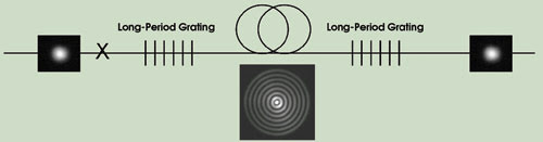
Figure 1. Light propagating in the fundamental mode (left) is converted with a long-period grating to a single high-order mode, where it can be amplified in an ultralarge-mode-area fiber. The large effective area of this fiber minimizes nonlinearities. After sufficient amplification, the single high-order mode is converted back to the fundamental mode (right).
Our technique involves a three-step arrangement (Figure 1). The signal is introduced into the fundamental mode of the fiber — a step similar to the conventional approach — which can be achieved with splices, collimation and/or focusing. Thereafter, the signal is transformed into the desired higher-order mode in an ultra-large-mode-area fiber with an in-fiber grating. Because the transformation involves converting a single lower-order mode into a single higher-order mode, it is achieved by resonant coupling — a highly efficient process with experimentally measured conversion efficiencies greater than 99 percent. After sufficient amplification has taken place in the ultra-large-mode-area fiber, the single high-order mode is converted back to a low-order mode.
Achieving large mode area
The effective mode area (Aeff ) of a fiber is defined by:
Aeff = [I • dA]2 / I2 • dA
where I is the intensity of the mode, and dA signifies integration over the cross-sectional area of the fiber. Commercial fibers with effective areas as large as ~800 μm2 are now achievable. One way to combat the instability that accompanies scaling to even larger mode areas is to decrease the index step that defines the waveguide, but this ultimately leads to very weakly guided modes that are, in turn, susceptible to bends and a host of other perturbations.
Laboratory demonstrations using this approach have achieved effective areas as large as 2000 μm2, but such demonstrations required great precision in input coupling and fiber handling4 — requirements that negate many of the robustness and high-reliability traits of fibers that make them attractive.
An alternative approach uses microstructured optical fibers in which the waveguiding mechanism is the same as in conventional fibers — total internal reflection. Even though microstructured optical fibers can be endlessly single-mode, their bend losses become prohibitively high as their effective areas are increased beyond 500 to 800 μm2. Thus, they also must be at least slightly multimode for designs with very large effective areas, but they offer greater design flexibility by selectively leaking higher-order modes.5 Effective areas up to ~1400 μm2 have been demonstrated. These results have been obtained in fibers that can be spliced and packaged and that represent a realistic candidate for future fiber lasers, but scaling to even larger effective areas suffers from the same limitations as conventional fibers.
A rigid glass rod variant of conventional fibers has gained much recent attention because a straight lightguide can clearly afford scaling of effective areas with low susceptibility to bending and mode coupling.6 These structures have achieved effective areas as high as 4500 μm2 but are limited to short lengths, require free-space coupling and are conceptually closer to conventional bulk solid-state rod lasers, although they offer better thermal management. In congruence with the aggressive large-mode-area fiber designs yielding 2000 μm2 effective areas, they negate some of the promise of high reliability and robustness that will be important in displacing existing solid-state lasers in many applications.
A stable fiber
The stability of large-mode-area fibers is governed by the extent to which random, distributed, resonant mode mixing between the desired mode and its nearest antisymmetric mode (LP1m mode, where m is the radial mode order) can be suppressed.
This suppression depends on two factors. It increases with the purity of launch into the desired mode, and, more importantly, random mode coupling is a resonant phenomenon that involves phase-matching between two modes. Hence, as the difference between the effective indices (neff ) of two modes increases, such coupling becomes increasingly inefficient.
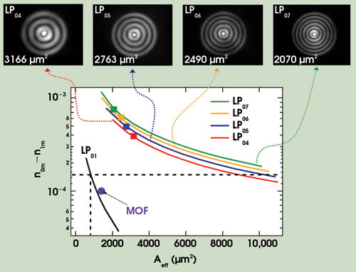
Figure 2. The effective index difference between nearest neighbors (stability proxy) versus effective area (Aeff ) is shown for different fiber platforms. Mode stability increases with modal order, as seen in the near-field images (top) after >2-m propagation with 7-cm bends, of long-period-grating-excited higher-order modes with effective areas from 2100 to 3200 μm2. MOF = microstructured optical fiber.
The solid black line in Figure 2 illustrates the trade-off between stability [i.e., lack of mode mixing, which grows with an increase in the difference of effective indices (n0m – n1m )] and effective areas for the LP01 mode of conventional fibers. Robust operation with conventional large-mode-area fibers is limited to effective areas ~800 μm2 because larger effective areas yield low enough n01 –n11 values so that mode coupling becomes prohibitively high (the dashed lines in the plot depict this demarcation).
Also shown is a data point denoted “MOF,” which illustrates the largest effective areas (~1400 μm2) reported in microstructured optical fibers.5 Although the difference in neff versus effective areas trade-off is similar to the conventional case, microstructured optical fibers can be designed with large differential modal losses. This enables radiating out the LP11 mode, yielding higher modal purity at the output. Hence, these fibers relax the constraint on conventional fibers and can offer stable operation for cases with significantly lower n01 – n11 values.
In contrast, operating with higher-order modes presents a unique design space to substantially scale effective areas. The colored curves in Figure 2 show the stability (n0m – n1m) versus effective area for four LP0m modes (m>1 denoting higher-order modes) in a few-mode fiber (index profile shown in Figure 3b). They exhibit a stability-versus-effective area trade-off, as do the conventional LP01 modes, but they dramatically differ on two accounts. The n0m – n1m values for higher-order modes are an order of magnitude higher than those for the LP01 mode, indicating the ability to obtain stable, mode-mixing-free signal propagation with significantly larger effective areas.
And more importantly, the n0m – n1m values increase with modal order (m), indicating that this concept is substantially scalable. The mode images shown in Figure 2 are experimentally recorded near-field images of grating-excited LP04, LP05, LP06 and LP07 modes, respectively, in a higher-order-modes fiber, with effective areas ranging from ~2100 μm2 (for LP07) to ~3200 μm2 (for LP04).
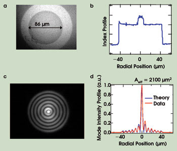
Figure 3. These images show the characteristics of a higher-order-mode fiber and the radiation it propagates. Horizontal and vertical scales of images and horizontal scales of plots are identical. The near-field image of a fiber facet shows its 86-μm inner cladding (a). The refractive index profile of a higher-order-mode fiber core is similar to SMF with 86-μm inner cladding, followed by a down-doped outer trench (b). The near-field image of LP07 mode at 1600 nm after 12-m propagation with 4.5-cm bends is shown (c), along with its intensity line scan and theoretical profile: Aeff ~2100 μm2 (d).
Figure 3 shows the details of a few-moded fiber of the type used to obtain the modal images in Figure 2, and one of the higher-order modes (LP07). The near-field image of the fiber facet and the corresponding refractive index of the profile in the figure show that the design comprises an inner-clad region of 86-μm diameter where the higher-order mode resides. The recorded near-field image of the grating-excited LP07 mode after ~12 m of propagation, and a corresponding intensity line scan with the theoretically predicted mode profile are also shown. The mode-intensity profiles are used to calculate the effective area of the mode, yielding 2140 μm2 for the simulation, compared with 2075 μm2 for the experiment. Additional experiments have revealed that stable mode propagation over 50 m, with bends down to 4.5-cm radii, can be achieved with this platform.
A critical component for this device is a long-period grating, which excites the desired higher-order mode as shown in Figure 1. The signal is coupled into the SMF-like core of the higher-order-mode fiber (Figure 3b). Such coupling can be achieved with very high modal purity and low loss using conventional splices. Thereafter, the signal is converted to the desired LP0m mode with a long-period grating. Long-period gratings are periodic index perturbations in a fiber that have periods ranging between 50 and 1000 μm. The resonant nature of this device ensures that the incoming signal is coupled only to the higher-order mode.
When the grating period is designed to match the beat length for coupling between two copropagating modes in a fiber, highly efficient coupling occurs from one mode to the other. This phenomenon has been exploited to make spectral loss filters in conventional fibers, where the fundamental mode carrying the signal is resonantly coupled to the single higher-order cladding mode. Because cladding modes are lost in the fiber coating, a loss filter is obtained in the spectral region where such coupling occurs. We use the same established technology to achieve mode conversion because the higher-order modes are well-guided (indeed, by design, because they are our preferred mode of signal propagation). Long-period gratings in the higher-order-mode fibers serve only to efficiently couple (but not attenuate, as in conventional fibers) the signal from the input fundamental mode to the desired higher-order modes.
The long-period grating in Figure 1 differs from conventional ones in one other aspect. One expects such resonant couplers to be highly efficient but very narrowband because they offer perfect phase matching only at a given wavelength. However, our studies have shown that the bandwidth of long-period gratings can be significantly extended if the group velocities of two modes can be matched (more generally, tailored). 7,8
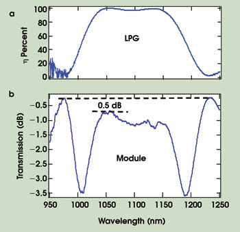
Figure 4. The long-period-grating coupling efficiency (η) is >90 percent over 137 nm, with peak coupling ~99.9 percent (a). Spectral output of the 3-m higher-order-mode module shows ~0.5 dB excess loss, primarily due to splices (b).
The long-period gratings illustrated exploit this group-velocity engineering aspect, and Figure 4a shows that the conversion efficiency to large-mode-area-higher-order modes from the fundamental mode is >99 percent, and the conversion can be achieved over bandwidths exceeding 100 nm.
Because gratings are reciprocal devices, an output long-period grating converts the signal back to a Gaussian shape. Hence, a module with the spectral characteristics shown in Figure 4b is obtained. Note that the broadband, efficient nature of the long-period grating, combined with the robust, spliceable nature of the higher-order-mode fiber yields a device with a 1-dB bandwidth exceeding 100 nm. The loss of the module is between 0.5 and 1 dB.
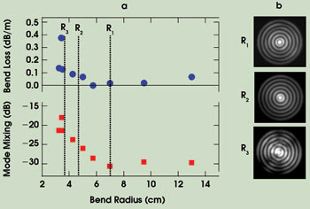
Figure 5. Higher-order-mode propagation is characterized in a 3-m-long fiber: Excess bend loss (top) and mode-mixing efficiency (bottom) versus bend radius (a) and near-field images for bend radius: R1 = 7 cm, R2 = 4.5 cm and R3 = 3.8 cm (b). No change is seen for R >7 cm; distortions are exhibited for R <4 cm. Stable modal output is observed down to a bend of R ~4.5 cm.
Figure 5a is a plot of the excess bend loss (top) and mode-mixing level (bottom — the mode-mixing level shown in decibels indicates the fraction of light in unwanted modes), respectively, as a function of bend radius, measured on a 3-m segment of a higher-order-mode fiber. The mode-mixing level was measured by recording the amplitude of fluctuations in the transmitted intensity.9 For bend radii >7 cm, the signal experiences immeasurably low bend losses, and mode-mixing levels remain below –30 dB (0.1 percent).
Thereafter, down to a bend radius of ~4 cm, the losses as well as mode-mixing amplitudes increase slowly, indicating the onset of small amounts of loss and mode-coupling. For bend radii <4 cm, the losses as well as mode-coupling rise rapidly. This is consistent with near-field images of the modal output recorded in the bent fiber. Figure 5b shows such images for bends of 7, 4.5 and 3.8 cm, respectively. Although modal images for bend radii down to 4.5 cm yield a pure LP07 output, that of the fiber bent to R = 3.8 cm shows distortions, presumably due to unwanted coupling to other higher-order modes.
Higher-order modes in specially designed few-mode fibers have two attractive attributes in addition to modal stability. The choice of modal order provides a variety of achievable effective areas (Figure 2). Because the inner-cladding layer that primarily guides the higher-order modes is a high-index-contrast waveguide, the mode remains tightly confined over a range of wavelengths.
The result is that the design is relatively agnostic to wavelength, and the effective area remains large (and similar) over a large spectral range. This is illustrated in Figure 6a, which shows the calculated effective area for the LP07 mode in a higher-order-mode fiber. Note that over a wavelength span of ~500 nm, the effective area changes by only 6 percent. Hence, these structures can be used to obtain robust, large-effective-area propagation in a wide range of technologically important wavelengths.
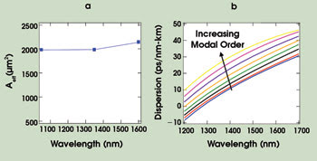
Figure 6. Design flexibility is possible with choice of modal order. The effective area (Aeff ) of the LP07 mode versus wavelength is shown, with less than 6 percent change in effective area across 500 nm (a). Dispersion increases with modal order, enabling the attainment of anomalous dispersion at 1060 nm.
The other interesting feature of this platform is the ability to tailor the dispersion of the mode. Dispersion tailoring of guided optical modes is well known in fibers and has been exploited in telecom applications to realize dispersion-shifted and dispersion-compensating fibers. However, dispersion tailoring with the conventional LP01 mode is restricted to designs that have relatively small effective areas (typically between 10 and 60 μm2). For large-mode-area designs, light in the LP01 mode resides exclusively in a large single-index guiding layer, and its dispersion is essentially that of the material in which it resides.
In contrast, it is well known that higher-order modes provide significantly greater design flexibility in dispersion tailoring. For small/standard-effective-area designs, this property has been exploited to achieve record-large negative dispersion,10 strong positive dispersion,11 and dispersion compensators with record figures of merit (FOM = dispersion/loss).8 Figure 6b shows the dispersion-tailoring flexibility of the large-effective-area higher-order modes described here. As mode order increases, the dispersion becomes increasingly positive, such that it may be feasible to obtain anomalous dispersion even at 1060 nm, a property of potentially great interest in constructing 1060-nm femtosecond lasers.
Unlike conventional LP01 modes, higher-order modes have nonmonotonic spatial distributions of light. In particular, the intensity of the central lobe is significantly higher than that of the rings (see Figure 3d for typical intensity profiles), and it may appear that this feature would make the higher-order modes more susceptible to nonlinearity. In fact, the peak intensity of a 2100-μm2 effective-area higher-order mode (Figure 3) is comparable to that of a conventional Gaussian mode with an effective area of only 300 μm2.
However, the factor primarily governing nonlinear distortions — such as stimulated Raman scattering, self-phase modulation or any nonlinear effect arising from the Kerr effect in silica fibers — is not peak intensity, but the value of effective area, defined in the equation above. An intuitive explanation is that it is not only high local intensity, but also the spatial extent of it that matters in determining accumulated nonlinear behavior. Thus, to first order, effective area is sufficient for describing the nonlinear behavior of light in a spatial mode, and because higher-order modes have been shown to possess record large effective areas, we expect them to be substantially resistant to nonlinearities.
One effect that may depend on local intensity rather than on effective area is dielectric breakdown — nanosecond pulses are especially susceptible to it.12 However, the peak intensity (as a ratio of total power) is different for different modal orders. Hence, the choice of modal order offers design flexibility, depending on which nonlinearity primarily has to be mitigated in a system.
Fully realizing the potential of higher-order modes will require additional investigation. Controlling the magnitude of the high-intensity central peak may call for judicious choice of mode order, and it remains to be seen whether enough design flexibility exists to avoid dielectric breakdown for millijoule pulse energies. In addition, this platform requires that light first be input in the small-effective-area LP01 mode, which may limit the input energy level that can be tolerated. But this may not be a severe limitation because the core can always be made to resemble the LP01 mode of a conventional large-mode-area fiber.
The true potential of this platform will be realized with the demonstration of an amplifier. In principle, this is a straightforward extension, but because the entire inner-clad region must be doped with the rare-earth dopant of choice, successfully creating an ultralarge effective area challenges conventional fiber fabrication.
Acknowledgment
The authors wish to thank J. Nicholson, J. Fleming, D. Trevor, P. Wisk, J. Fini, E. Monberg, F. Dimarcello and D. DiGiovanni for helpful discussions. This work was performed under the support of the US Department of Commerce, National Institute of Standards and Technology, Advanced Technology Program, Cooperative Agreement No. 70NANB4H3035.
Meet the authors
Siddharth Ramachandran is distinquished member of technical staff at OFS Laboratories in Somerset, N.J., the research arm of OFS-Fitel LLC; e-mail: [email protected].
Samir Ghalmi is a member of technical staff at OFS Laboratories in Somerset, N.J.; e-mail: ghalmi@ofsop tics.com.
Man F. Yan is a technical manager at OFS Laboratories in Murray Hill, N.J.; e-mail: [email protected].
References
1. A. Galvanauskas (2001). Mode-scalable fiber-based chirped pulse amplification systems. IEEE J SEL TOP QUANT ELECTRON Vol. 7, p. 504.
2. M.E. Ferman (1998). Single-mode excitation of multimode fibers with ultrashort pulses. OPT LETT, Vol. 23, p. 52.
3. S. Ramachandran et al (2006). Light propagation with ultra-large modal areas in optical fibers. OPT LETT, Vol. 31, p. 1797.
4. K-H. Liao et al (2006). Diffraction-limited 65-μm core Yb-doped LMA fiber based high energy fiber CPA. Proc. CLEO 2006, post-deadline paper CPDB4.
5. J.S. Wong et al (2005). Breaking the limit of maximum effective area forrobust single-mode propagation in optical fibers. OPT LETT, Vol. 30, p. 2855.
6. J. Limpert et al (2006). Extended single-mode photonic crystal fiber lasers. OPT EXP, Vol. 14, p. 2715.
7. S. Ramachandran et al (2002). Bandwidth control of long-period grating-based mode-converters in few-mode fibers. OPT LETT, Vol. 27, p. 698.
8. S. Ramachandran (2005). Dispersion-tailored few-mode fibers: A versatile platform for in-fiber photonic devices. J LIGHTWAVE TECH, Vol. 23, p. 3426.
9. S. Ramachandran et al (2003). Measurement of multi-path interference in the coherent cross-talk regime. IEEE PHOTON TECH LETT, Vol. 15, p. 1171.
10. S. Ramachandran et al (2005). High energy (nanojoule) femtosecond pulse delivery with highly dispersive higher order mode fibers. OPT LETT, Vol. 30, p. 3225.
11. S. Ramachandran et al (2006). Demonstration of anomalous dispersion in a solid, silica-based fiber at λ <1300 nm. Proc. OFC, post-deadline paper PDP3.
12. B.C. Stuart et al (1995). Laser-induced damage in dielectrics with nanosecond to sub-picosecond pulses. PHYS REV LETT, Vol. 74, p. 2248.