Research is focusing on extending infrared scene projection dynamic range and developing an emerging class of quantum/photonic infrared scene projection devices with improved combinations of radiance and speed.
Paul Bryant, Left Coast Consulting, and Steve Solomon, Acumen Scientific
Over the past three decades, infrared scene projection has evolved into a critical laboratory tool for evaluation of high-performance infrared imagers and their embedded algorithms.
This technology projects accurate, realistic and dynamic IR scenes into the entrance aperture of the sensor being tested. It is used to simulate the operating environment of various systems, including imaging infrared missile seekers, search and track systems, and thermal imagers.
Using it for hardware-in-the-loop simulation has reduced the scope and cost of flight/field testing, while enabling a new level of sensor optimization. Hardware-in-the-loop simulation enables the generation of synthetic IR imagery for laboratory evaluation of high-performance electro-optical systems (Figure 1).
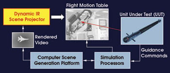
Figure 1. Hardware-in-the-loop simulation is used to create a synthetic representation of real-world dynamic imagery. A typical architecture is shown here. Courtesy of Santa Barbara Infrared.
The quest for viable IR scene projection technologies began in the 1970s. Early devices included the Bly cell, the liquid crystal light valve, resistor arrays, Texas Instruments’ digital micromirror device, deformable mirror and scanned laser devices, the IR CRT, vanadium dioxide spatial light modulators and laser diode arrays (Figure 2). Over time, resistive arrays have emerged as the leading technology for the most stressing IR scene projection applications.
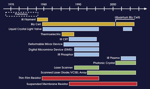
Figure 2. Infrared scene projection technology development began in the 1970s.
Research is proceeding to extend the dynamic range of existing IR scene projection architectures and to develop an emerging class of quantum/photonic IR scene projection devices with a better combination of radiance and speed. A cyclical process of sensor and projector advancement is expected to continue, to the benefit of advanced sensor and simulator developers.
Modern IR scene projection systems project high-resolution (1024 × 1024 and up), high-temperature (700 K+) dynamic IR imagery with up to 16-bit input resolution. Emerging IR scene projection systems will provide wide-format (768 × 1536), cryogenic background (50 to 80 K), fast-framing (>400 Hz) and very high temperature (2500 K) dynamic IR simulation capabilities.
Simulations that require high dynamic range and thermal resolution use 14- to 16-bit dynamic IR scene projection systems based upon resistive microelectromechanical systems (MEMS) array technology. For applications with more modest requirements, lower-cost systems based upon reflective MEMS technologies (such as the digital micromirror device) commonly provide 8- to 10-bit simulation solutions. A variety of new technologies are in various stages of development to address the most challenging IR scene projection requirements of the future.
Infrared scene projection technologies can be divided into three categories: thermal, modulation-based and quantum/photonic. Thermal technologies include thin-film, bridge- and suspended-membrane resistors; Bly cells; and thermoelectric devices that create IR radiance through physical temperature and emissivity. Modulation-based IR scene projections use reflective spatial light modulator devices, including the digital micromirror device; transmissive spatial light modulators, such as the liquid crystal light valve; or galvanic cell devices with external illumination. Quantum-/photonic-based simulators use laser, LED, plasma and/or photonic crystal technologies to create high-intensity, narrowband illumination patterns.
Advanced simulations often require high frame rates (>400 Hz) with minimal spatial-temporal image artifacts. Snapshot and raster update modes allow synchronization with both scanning and staring sensors under test. Infrared scene projector pixel operability must typically exceed 99 percent with few clusters, while fast temporal performance maximizes radiometric stability.
Thermal technologies
The resistive emitter array has evolved from its early microbolometer roots into the leading IR scene projection technology. Infrared scene projections based on these “bolometers running backward” produce broadband IR imagery with a high dynamic range, high thermal and spatial resolution, and flickerless operation.
Each resistive emitter pixel is a suspended MEMS structure consisting of a resistor supported by two thermally insulating legs, optically enhanced by an underlying etalon structure (Figure 3). Pixel arrays are fabricated monolithically onto CMOS ASIC substrates and current-driven on a per-pixel basis to produce Joule heating and IR emission.
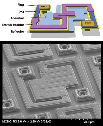
Figure 3. Each resistive emitter MEMS structure is a resistor supported by two thermally tuned legs. Courtesy of Santa Barbara Infrared.
The maximum simulated temperature of resistive array-based IR scene projection systems is 700 to 800 K (MWIR) and 500 to 600 K (LWIR), with 14-bit resolution of roughly 20 mK. Development is under way to extend the temperature range to 2500 K, the effective temperature of a late M-class star! Although maximum temperatures are rising, space-based interceptor hardware-in-the-loop testing requires minimum temperatures that are cryogenic (50 to 80 K).
Such arrays must operate at very low substrate temperatures while providing the same maximum output as standard systems. Radiance rise/fall time is approximately 5 ms, with scene-dependent crosstalk in the range of 1 to 3 percent. Achieving these levels of performance has required significant development in CMOS design/fabrication and MEMS materials, processing and robustness.
Modulation-based technologies
The leading reflective IR scene projection technology is Texas Instruments’ digital micromirror device — a two-dimensional array of bistable MEMS-based mirrors, electrostatically actuated and digitally addressed (Figure 4, left). An off-axis IR source illuminates the digital micromirror device, with each pixel directing light toward (or away from) a projection optics pupil. Gray-scale imagery is produced via pulse width modulation (Figure 4, right).
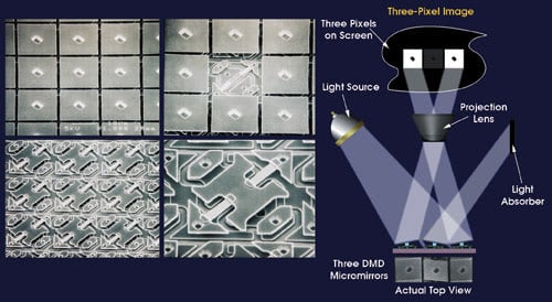
Figure 4. The digital micromirror device is a 2-D array of bistable MEMS mirrors (left). The process for producing 2-D gray-scale images is shown on the right. Courtesy of Texas Instruments.
Digital micromirror device amplitude resolution and frame rate are inversely related and limited by each pixel’s pulse width modulation cycle time. Infrared scene projectors based on these devices typically provide 8-bit resolution at 200 Hz, 10-bit at 60 Hz, 11-bit at 30 Hz and so on. Maximum apparent temperature is approximately 800 K (MWIR) and 400 K (LWIR), with 0.1- to 0.5-K resolution at 200 Hz.1
Other reflective spatial light modulator technologies, such as analog MEMS mirror arrays, have been demonstrated for telecom applications and may someday move beyond the digital micromirror device’s resolution, frame rate and flicker limitations — assuming sufficient CMOS and MEMS investment. Diffractive spatial light modulator technologies such as the grating electromechanical system offer the potential for novel multi- and hyperspectral IR scene projection implementations.2
A plasma, or microdischarge, display is a pixilated array of microcavities, each containing a gas mixture electrically “ignited” to form a plasma (Figure 5, left). Microdischarge technology offers a unique approach to creating very bright, spectrally agile, high-speed two-dimensional displays. Spectral content is determined by the gas species, partial pressures and excitation conditions, with gray-scale resolution attained via pulse width modulation. Simple architectures can produce radiance from the solar-blind UV through the far-IR. A single optoelectronic subsystem may be used for UV-LWIR projection by simply swapping gases/projector focal plane assemblies. This technology is under development.3
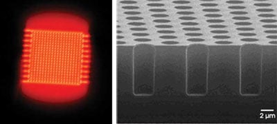
Figure 5. A plasma display is an array of microcavities containing a gas mixture that is ignited to form a plasma (left). Photonic crystal devices compress broadband emission into a narrow range (right). Left image courtesy of Acumen Scientific. Right image courtesy of the University of Illinois at Urbana-Champaign and of Ion Optics.
Photonic bandgap, or photonic crystal, devices “compress” broadband emission into a narrow spectral range such that each pixel appears brighter than its physical temperature would suggest (Figure 5, right). Photonic crystal-based IR scene projectors currently require Joule heating to create thermal emission for subsequent spectral conversion. Devices consist of periodic arrangements of metallic and dielectric structures that selectively enable the propagation of light in specific directions, over spectral bands defined by device geometry and materials. Tuning is accomplished by index of refraction modulation, or “hole,” geometry selection. Photonic crystal devices also may be operated in reflective mode, whereby a thermal illumination source spectrum is spectrally compressed and reflected by the photonic crystal mirror.
Lasers and LEDs are well suited to simulate discrete hot objects because of their intrinsic brightness.4,5,6 Small arrays have been assembled to simulate “hot spots,” and fiber-coupled lasers have produced 106 dynamic range with apparent temperatures approaching 3000 K. Lasers have been beam-combined with large-format projectors for wide-field simulation with superimposed hot spots.7 Unfortunately, current fabrication techniques and device geometries preclude the manufacture of large-format LEDs and lasers for IR scene projection use. Furthermore, laser and LED efficiencies are very low, requiring excessive cooling in large formats.
System issues
Infrared scene projection development has faced many challenges. Large resistive arrays draw high peak currents (up to 200 A) and dissipate up to 1000 W, requiring systems to handle such loads reliably.8 Large, fast arrays also stress data throughput, requiring more than 3 Gb/s with real-time digital signal processing. A number of sophisticated processing engines9 have recently addressed this need.
Some infrared scene projection applications can tolerate the image flicker of pulse width modulation-based technologies such as digital micromirror devices and plasmas. Certain applications require broad spectra, while others can utilize the narrowband emission of LEDs, plasmas and photonic devices. Some units undergoing testing require fast-framing projectors, while others can tolerate the slower image refresh of commercial off-the-shelf solutions.
Infrared scene projectors are usually calibrated radiometrically rather than thermometrically. Recent strides in radiometric calibration and real-time nonuniformity correction have improved accuracy, spatial uniformity, stability and repeatability.6
In an ongoing development cycle, imagers and projectors continue to play “leapfrog,” leveraging each other’s breakthroughs and extending the state of the art for future units undergoing testing and for the testers themselves.
Simulating hot objects such as engine exhausts, rocket plumes and countermeasures requires temperatures not currently attainable. Pixel materials ultimately limit maximum temperature. Current IR scene projectors simulate up to approximately 800 K, beyond which material instability causes pixels to melt or sublimate. Fabrication of high-temperature emitters will require thin-film-compatible materials with carefully selected thermophysical properties. Simulated temperatures in the 2000- to 3000-K range are expected this year.10
The emergence of simultaneous multiband IR detectors will require next-generation IR scene projections to project multispectral scenes. Interim simulation solutions have relied on the optical combination of multiple emitter arrays into a single multicolor scene. Although optically combined single-color IR scene projectors are bridging this test and evaluation gap, many novel multicolor projector technologies will be demonstrated over the next several years.
Meet the authors
Paul Bryant is president of Left Coast Consulting in Santa Barbara, Calif.; e-mail: [email protected].
Steve Solomon is president of Acumen Scientific, also in Santa Barbara; e-mail: [email protected].
References
1. D.B. Beasley et al (May 2005). Technologies for synthetic environments: Hardware-in-the-loop testing X. Proc SPIE, Vol. 5785, pp. 68-79.
2. J.C. Brazas and M.W. Kowarz (January 2004). High-resolution laser-projection display system using a grating electromechanical system (GEMS). Proc SPIE, Vol. 5348, pp. 65-75.
3. R. Ginn et al (May 16, 2006). Visible/UV image projector for sensor testing. Proc SPIE, Vol. 6208, 62080O.
4. P. Halevei and F. Ramos-Mendieta (August 2000). Tunable photonic crystals with semiconducting constituents. PHYS REV LETT, Vol. 85, pp. 1875-1878.
5. Kang et al (April 2001). Electro-optic behavior of liquid-crystal-filled silica opal photonic crystals: Effect of liquid-crystal alignment. PHYS REV LETT, Vol. 86, pp. 4052-4055.
6. N.C. Das et al (May 16, 2006). MWIR LED array for high temperature target simulation. Proc SPIE, Vol. 6208, 62080N.
7. J. Geske, private communication.
8. P. Bryant et al (May 2005). MIRAGE: developments in IRSP systems, RIIC design, emitter fabrication, and performance. Proc SPIE, Vol. 5785, pp. 1-13.
9. O.M. Williams et al (May 16, 2006). Resistor array infrared projector temperature resolution: revisted. Proc SPIE, Vol. 6208, 62080V.
10. S. Solomon et al (May 16, 2006). High temperature materials for resistive infrared scene projectors. Proc SPIE, Vol. 6208, 62080S.