A commercial compact digital interferometer, directly mounted on an ultraprecision diamond-turning machine, offers an alternative to today’s stylus-based machine-integrated measuring systems and provides fast noncontact testing of optical surfaces.
Thomas Blümel, Fisba Optik GmbH, Berlin, and Markus Bosse and Martin Kurz, IWF, Technical University Berlin
Interferometers often are seen as laboratory instruments, requiring rooms with controlled environments, skilled operators and adequate space. Apart from the fact that this is not necessarily true of all devices on the market, integration of interferometric sensors directly into production lines still is a challenge because they face harsh conditions — dirt, dust, vibration, temperature variances, ambient light. Furthermore, production line integration requires that sensors be compact, robust, adaptable and able to operate in any direction and to deliver results quickly.
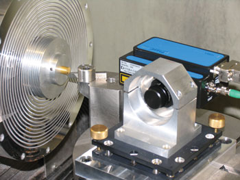
Figure 1. The interferometer is integrated into an ultraprecision diamond-turning machine. The μPhase is mounted on the tool axis.
When the sensor cannot be integrated directly into the production machine, the solution often is to place it near the machine and to render the environmental conditions as benign as possible. Just as important as the physical integration of the measurement sensor in or near the production machine is an open and well-documented interface to control a number of devices and to exchange data and parameters among them.
What makes an interferometer so powerful as a measuring device, especially in optics production, is its ability to measure deviations at the nanometer range and over the illuminated 2-D area. So, compared with scanning devices, its measurements are very quick. Another advantage of interferometry is a noncontact measurement that avoids damage to the sample.
However, certain issues must be addressed when using interferometers in a production environment. The first one is surface quality. The sample to be tested must have an optical surface that directly reflects the incoming light. Samples with a surface that shows diffuse reflection cannot be measured with an interferometer.
Interferometric measurements are extremely sensitive to environmental vibrations; hence, the interferometer must be isolated from them, and the connection between sample and interferometer should be rigid.
Interferometry’s very high accuracy comes at the expense of a limited dynamic range, requiring good positioning precision of the interferometer relative to the measured part. Thus, a high-precision positioning device may be required in the production process, which, in some cases, also can be used to position the interferometer or the part automatically. In this context, it is also worth noting that, because of the interferometric measurement principle, interferometers are best adapted to measuring flat and spherical shapes. Testing other shapes requires special optics and analysis algorithms.
Measurement results
Another consequence of the interferometric measurement principle is the form of the measurement results. When measuring with a spherical setup, the resulting data is specified as deviation from a sphere, thus as spherical coordinates. However, production machines work extensively in Cartesian coordinates, making it necessary to convert the interferometric measurement results for further use in the machine.
To demonstrate the capabilities of a commercial compact digital interferometer, a Fisba μPhase system was mounted directly onto a five-axis ultraprecision Nanotech 350 FG lathe from Moore Nanotechnology Systems LLC. Such machines generate surfaces whose optical quality has global shape deviations better than 1 μm, which often are used for master piece production or for manufacturing of moulding tools.
The lathe was equipped with a rotatable tool axis on which the interferometer was mounted. The existing machine axes were used to bring the interferometer into its measurement position. Only the horizontal tilt had to be adjusted manually after mounting. Switching between processing the sample and measuring was achieved simply by rotating the tool axis. During the machining of the part, the interferometer remained on the machine. The lens was protected by a cover to avoid damage and contamination by loose swarf. To ensure a high repositioning accuracy, the connection cables of the interferometer were led out of the lathe without strain.
A very important step when fine-tuning an ultraprecision lathe is adjusting the tool, which must be done every time it is changed. To adjust the tool, its exact position in reference to the workpiece must be determined. Its position in reference to the turning axis consists of a horizontal (X tool offset) and a vertical (Y tool offset) component, and the exact tool offset (X and Y) can be determined only indirectly.
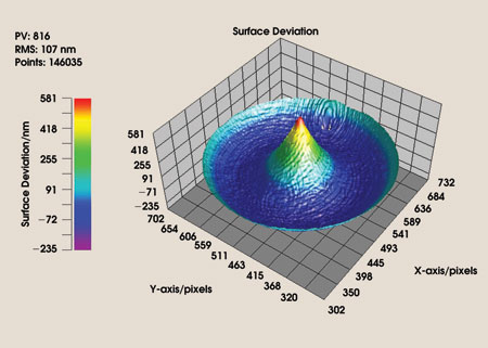
Figure 2. This example shows the measurement of the tool position relative to the workpiece using an online interferometer for a typical cone-shaped tool with an offset of 50 μm.
A tool offset causes typical errors in the shape of a sample. These errors traditionally are measured by a microscope or a white-light interferometer but are usually taken outside of the machine. As a result, the tool offset must be optimized in several steps in a procedure that is very time-consuming because the workpiece must be adjusted on the lathe every time. It also requires an experienced operator to interpret the measurement results.
With the new interferometer arrangement, the X component of the tool offset can be measured interferometrically with high accuracy. The possibility of measuring the tool offset with the integrated interferometer directly on the machine was tested. Systematic tests showed that the X tool offset could be determined with an accuracy of 1 to 2 μm, which is comparable to — or even better than — that achieved by traditional measurement techniques.
When integrating an interferometer directly on a lathe, the next logical step is to use the measurement results of the interferometer to establish a direct in-line correction of the workpiece without loss of accuracy, which otherwise is inevitable after taking the sample off and replacing it again on the machine after an offline measurement.
To test this functionality, a sample with a sinus-shaped error was manufactured and measured. A correction function was calculated from the measurement results, and the sample was diamond-turned again using the correction function. The results show that the error was almost completely corrected. The remaining deviation was caused by the limited repeatability of the turning process and by small errors in the scaling of the measurement results.
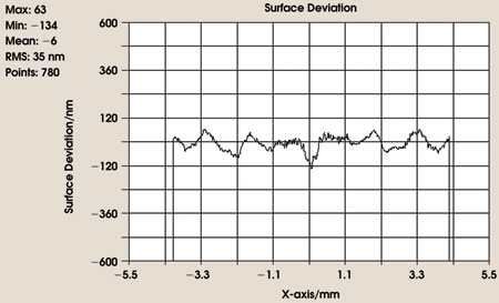
Figure 3. The correction of a sinus-shaped error was used to verify the in-process correction capabilities of the integrated measurement system.
The results of this first demonstration of the cooperation of an interferometer and an ultraprecision lathe show that there is great potential in using compact interferometers in this type of production environment. The interferometer also can be used for measuring and correcting the sample as well as for optimizing the machine’s tool offset, reducing setup time and increasing production quality. It also can be integrated completely into the work flow of the lathe, and control loops can be applied to optimize the processing until the sample has reached the desired quality.
Contact: Thomas Blümel, Fisba Optik GmbH; fax: +49 30 6392 3452; e-mail: [email protected].