TIRF microscopy can deliver powerful results, but the challenges in specimen preparation and equipment capabilities must be kept in mind.
Nicolas B. George, Olympus America Inc.
Total internal reflection fluorescence (TIRF) microscopy is a powerful technique. It provides extremely thin axial sectioning with excellent signal-to-noise ratios, allowing observation of fluorescent events occurring at the interface between two media with different refractive indices.
Total internal reflection can occur when excitation light reaches an interface of a medium with a higher refractive index and a lower refractive index at an angle of incidence greater than a specific critical angle. When the light is totally internally reflected, none penetrates the lower-refractive-index medium; however, the reflected light generates an electromagnetic field that penetrates beyond the interface as an evanescent wave, into the lower-refractive-index medium. This wave decreases exponentially with distance into the media and penetrates only ∼100 nm beyond the interface. It can be used to excite fluorescence in objects within the evanescent section (Figure 1). The evanescent wave can be made even thinner by increasing the angle of incidence beyond the critical angle.
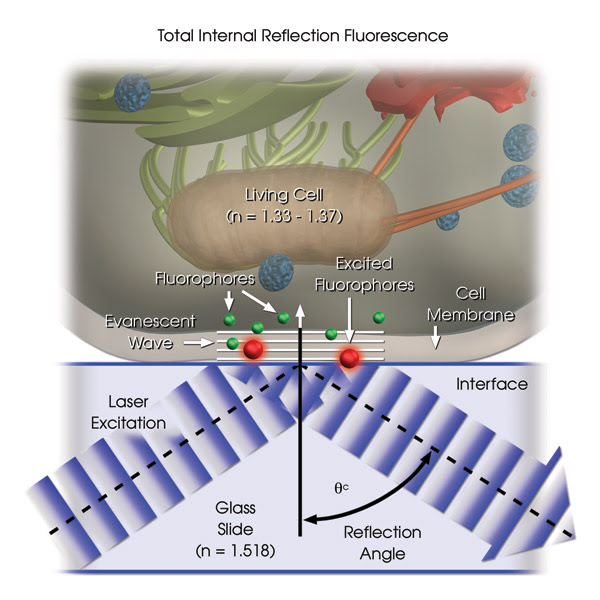
Figure 1. A schematic depiction of a TIRF setup shows selective excitation of fluorophores in a tissue culture cell (refractive index of 1.33 to 1.37) resting on the surface of a glass slide (refractive index of 1.518). Wavefronts from a laser excitation source pass through the glass and are reflected from the glass-buffer boundary at a critical angle, q(c), establishing an evanescent wave that travels approximately 100 nm into the cell. Fluorophores in the cell near the glass interface (shown here as small green spheres) are excited by the evanescent wave and subsequently emit fluorescence (depicted here in red), while those farther from the interface are not excited. Illustrations courtesy of Michael W. Davidson, Florida State University.
The power of TIRF microscopy lies with the extremely thin axial region of fluorescence excitation — “optical sectioning” — that allows imaging with very low background and minimal out-of-focus fluorescence. TIRF microscopy systems are either prism- or objective-based.
Prism-based systems use an external prism to achieve the critical angle of incidence. They are relatively easy to set up but may require elaborate methods of sample placement and manipulation. Typically, the prism used to create the critical angle is on the opposite side from the objective, making imaging difficult because the system is focusing through the entire cell to image the cell surface on the opposite side. These systems also can limit researchers to low-numerical-aperture, dry objectives.
Objective-based systems use the outer edge of an objective’s back focal plane to provide a column of light that exits the front of the lens at and beyond the critical angle. These systems, which use oil-immersion objectives with a high numerical aperture, are increasing in popularity because they lend themselves well to live cell preparations in coverslip-bottom dishes, and the researcher can image the specimen from the same side where the evanescent wave occurs.
Objective-based TIRF imaging of living cells is typically achieved by focusing a laser beam at the back focal plane of the objective. The angle of incidence for the column of light exiting the objective is increased by steering the focused laser spot toward the outer edge of the back focal plane. The numerical aperture of the objective must be higher than the refractive index of the second medium (NA >1.37 for aqueous mounts). For practical purposes, objective-based TIRF requires oil-immersion optics with numerical apertures of at least 1.45. Objective-based systems also present several interesting challenges, both in terms of sample preparation and with regard to the equipment and optics used.
The first series of challenges facing scientists using objective-based TIRF relates to how the sample is prepared and how cells are cultured. Cleanliness is of primary importance; the underside of the dish must be uncontaminated, and any fingerprints or old oil from prior work must be completely removed. Bubbles in the immersion oil must be avoided. If the cells have been cultured for a long time, they can develop confluence that prevents the areas of interest within the cells from experiencing the evanescent wave.
And, finally, many researchers like to coat the dishes with polylysine or collagen to aid cellular adhesion, but these coatings are of a higher refractive index than water or cytoplasm; if laid down too thickly, they may cause enough light scatter that the background signal becomes noticeable.
A second area of sample-related imaging issues with TIRF can arise when large, heterogeneous cellular organelles with a high refractive index are within the evanescent field. The organelles can result in the evanescent field becoming scattered, propagating light.
As noted by Daniel Axelrod, professor emeritus at the University of Michigan in Ann Arbor, both of these specimen challenges can negatively affect the quality of a TIRF image, but the severity can vary from insignificant to unacceptable.1
Equipment-related challenges
TIRF microscopy also faces several equipment-based challenges. The technique depends on a number of experimental variables that can be daunting for the researcher to control. First, the excitation light must pass through high-refractive-index media (immersion oil/cover glass; typical refractive index of 1.515) and on to a lower-refractive-index medium (usually an aqueous mounted specimen with a typical refractive index of ∼1.33 to ∼1.38). Mounting media with a refractive index higher than approximately 1.4 is not suitable for most objective-based systems.
The formula for depth of penetration of the evanescent wave is:
d = l(o)/4π • (n(1)2sin2q(1) – n(2)2)–1/2
where d is the depth of penetration, l(o) is the wavelength of the incident illumination in a vacuum, n(1) is the refractive index of the medium of illumination incidence, n(2) is the refractive index of the specimen medium’s refractive index (always lower than n(1)), and q(1) is the angle of illumination. Importantly, the equation indicates that the depth of penetration is dependent upon not only the refractive indices of the media but also the wavelength of excitation light used. For the researcher looking at multiple colors of fluorescence, as the wavelength of excitation light changes, the angle of incidence also must change to maintain the same depth of penetration.
The depth of penetration formula also assumes that the light in a vacuum and that of the sample’s exact refractive index is known — parameters that rarely can be obtained or quantified. Indeed, the glass coverslip and immersion oil usually are the only known refractive indices in the real world — and even these may not be consistent. We can calculate theoretical numbers for depth, but necessity dictates that there is some estimation involved. As a result, TIRF systems, especially those that are motorized, make assumptions as to the depth of penetration for any particular angle setting.
These issues are closely related to not knowing with certainty the critical angle for TIRF illumination. As the incident angle of light slowly increases, it reaches a critical angle for TIRF. The critical angle is defined by the equation:
sinq(c) = n(2)/n(1)
which is more commonly expressed as
q(c) = sin–1n(2)/n(1) = sin–1n(2,1)
Again, uncertainty about the refractive index of the media prevents accurate calculations of the exact critical angle necessary to achieve TIR, even when the system is achieving TIRF.
Multiple colors, angles
The issues inherent in all TIRF imaging become especially challenging when dealing with multicolor, multiangle TIRF. To keep the depth of penetration the same when changing wavelengths, the angle of illumination must be adjusted for every color. Most systems are limited to a single fiber delivery system to introduce laser light to the microscope. These illumination systems are limited to one angle and one focus setting. Any wavelength-dependent shifts in angle or focus must be addressed when different colors are introduced.
Some systems offer a motorized angle adjustment system to automate the necessary adjustment when changing wavelengths. Although initial setup of the systems can be complex, they require just a few mouse clicks to capture images. However, where multiple users with varying projected needs are involved, or for users who think their needs may someday be more advanced, today’s motorized systems may be too limited. First, motorized TIRF systems are restricted when observing intracellular processes in living cells. Because they are limited to one angle and focus setting, true simultaneous capturing of multiple fluorescence wavelengths is impossible because of the lag time required to adjust the angle between colors. There can be a substantial lag (in the tens to hundreds of milliseconds) when switching from one color to the next. Also, for monitoring dynamic processes in cells, such as colocalization studies, it is impossible to accurately and completely superimpose various color images taken at different times; temporal resolution is reduced.
Another issue to be considered is chromatic aberration, which occurs because different colors of light have different angles of refraction when passed through a lens and therefore are not brought into focus at the same focal point. The optical elements of the illumination system and objective are designed to minimize this aberration. Objective-based TIRF systems can be sensitive to any changes in excitation beam focus/position as a result of chromatic aberration. One effect of chromatic aberration is a poorly collimated beam exiting the objective, which signifies light rays exiting the objective at different angles (Figure 2). Chromatic aberration effects can be corrected for each wavelength by setting the illuminator focus and/or angle of incidence for each excitation color.
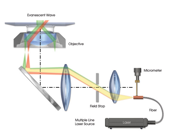
Figure 2. A TIRF illumination system is shown with exaggerated chromatic aberration resulting in a displaced focal point of the laser source on the back focal plane of the objective. The difference in angle for the collimated beams exiting the objective results in the green beam achieving total internal reflection, while the red beam continues to travel deep into the specimen.
One elegant solution to these issues is to use a total internal reflection illumination system that has a dedicated fiber and focusing system for each color of excitation light. Such a system allows the researcher to optimize each color uniquely and independently, permitting simultaneous multiple color imaging while maintaining those settings.
The new Olympus multicolor, multiangle OMAC TIRF system offers up to three independent illumination/fiber delivery points. There are two- and three-laser-line versions, with each having its own angle and focus adjustment. True simultaneous imaging is thus possible using up to three colors at the same time. A researcher can easily correct for critical angle and chromatic aberration. Such systems are appropriate for both single and multiuser systems because they offer higher image quality and can accommodate users from the lowest to the highest levels. For researchers whose work involves capturing movies or time-lapse sequences of TIRF specimens, such capability is even more important; when imaging over time, it is imperative to have true multiangle ability. The company also offers five objectives optimized for TIRF applications, including a 60x 1.49-NA lens, and other high-NA objectives at 60×, 100× and 150× — all compatible with the multicolor, multiangle system.
For all its potential, TIRF imaging provides enormous challenges for optical designers and for researchers employing the technique. Some researchers are using atomic force microscopy to begin measuring the depth of penetration of the evanescent wave, but the loop has not been closed on this question yet. The barriers presented by specimen preparation issues and equipment remain some of the most thorny and important challenges in live-cell imaging. Despite its complexities, however, TIRF remains one of the most productive and useful imaging methodologies available to scientists today.
Acknowledgment
The author wishes to acknowledge Dr. Kenneth N. Fish of the University of Pittsburgh for his support in the development of this article.
Nicolas B. George is the group marketing manager of light microscopy at Olympus America Inc. in Center Valley, Pa.; e-mail: [email protected].
Reference
1. D. Axelrod (November 2001). Total internal reflection fluorescence microscopy in cell biology. TRAFFIC, pp. 764-774.