Novel techniques using lasers, LEDs and fiber optics aid protein separation and analysis.
Lynn M. Savage, News Editor
As a tool for divining all that is knowable about proteins, capillary
electrophoresis has taken a strong grip on investigators. The technique offers scientists
from oncologists to pharmacologists speedy and sensitive separation of proteins
— either inside narrow tubes or within the etched walls of a microfluidic
chip — and a number of methods have been developed to detect and analyze the
proteins within a sample, including laser-induced fluorescence.
But there is always room for improvement. Researchers
continuously seek ways to reduce both the size of bulky equipment and the costs
of analytical systems and, most importantly, to improve the speed and sensitivity
of the process so that protein analysis can reveal more information.
Optical injection
Traditional sample injection in capillary electrophoresis
involves physical manipulation of the separation capillary into and out of vials
containing buffer or sample, making the process slow and difficult to reproduce.
These limitations have led to the development of so-called gating techniques that
enable injection into a continuously flowing solution. Gated injection — whether
by mechanical or optical means — segments an analyte within a buffer into
easy-to-analyze chunks that then pass within view of a detector, such as a laser
beam.
In optically gated capillary electrophoresis,
the sample to be studied is tagged with a fluorescent dye, added to a buffer solution
and continuously streamed under the high-voltage electrical field. A high-power
laser photobleaches the analyte as it passes by the beam’s target area. By
intermittently blocking the laser beam, a select amount of actively fluorescent
analyte can be detected by a second laser farther down-stream.
Although this method provides faster
processing times than traditional, nongating methods, the photobleaching step rarely
is more than 90 percent efficient. Inefficient bleaching leads to significant background
fluorescence at the detection stage and, thereby, to lower sensitivity.
In the June 1 issue of Analytical
Chemistry, Craig A. Aspinwall and his colleagues at the University of Arizona
in Tucson describe an alternative approach that puts a twist into standard optical
gating.
The researchers tagged analytes with
a fluorophore that was “caged” via covalent attachment of a pair of
nitrobenzyl groups to a molecule of fluorescein to inhibit fluorescence. When added
to buffer running through a capillary electrophoresis system, the analyte was effectively
invisible to the filtered 488-nm detection beam from an argon-ion laser made by
Coherent Inc. of Santa Clara, Calif.
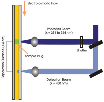
Figure 1. A schematic of a photolytic optical injection method for
capillary electrophoresis depicts laser beam orientation.
However, when the cages were removed
via photolysis with the 351- to 364-nm lines split off from the same beam, the fluorescence
was reactivated and the analytes became detectable. The investigators directed
the focus of the photolytic beam onto the capillary for periods of 5 to 20 ms using
a mechanical shutter and collected fluorescence using a 20x, 0.4-NA objective from
Melles Griot and a photomultiplier tube from Hamamatsu Photonics in Bridgewater,
N.J. (Figure 1).
According to Aspinwall, using photolysis
to activate fluorescence reduced background noise by as much as 10,000 times, with
a corresponding increase in sensitivity that should enable detection of neuropeptides
and other proteins that are difficult to elucidate (Figure 2).
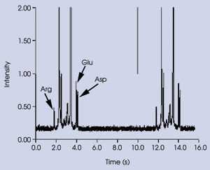
Figure 2. During the separation of amino acids labeled with caged
fluorescein using a photolytic optical gating technique, consecutive online injections
were performed on a sample mixture containing 50 nM labeled arginine (Arg), glutamic
acid (Glu) and aspartic acid (Asp). Lines in upper trace indicate times of injection.
E = 1.77 kV/cm; injection time = 20 ms.
After uncaging, the analytes separate
as they travel from the site of the gating beam to that of the detection beam. In
the setup, the discrete photolytic and detection laser lines were spaced 1.4 cm
apart along the capillary. The investigators would like to shrink that distance,
which thus far is limited by the physical constraints of the filters and other optical
components that they employed. “Shorter separation paths yield higher speed,”
Aspinwall said. “Ideally, one would like to use subcentimeter separations.”
The researchers are focusing on three
approaches to improve their technique. They are exploring the use of LEDs to provide
the UV and blue wavelengths now generated by the laser, developing caged fluorescent
labels that have faster reaction dynamics and integrating the system into a microfluidic
platform.
Getting the LED in
Aspinwall’s group is, by no means, the only
one looking to LEDs to replace lasers in capillary electrophoresis systems. Given
the ongoing drive to reduce the size and cost of protein analysis, lasers —
even solid-state diode devices — are bulky and expensive. Antonio Segura-Carretero
of the University of Granada in Spain, said LEDs are “an exceptionally attractive
stable excitation light source for luminescence detection in capillary electrophoresis.”
He and his colleagues in Alberto Fernández-Gutiérrez’s
research group in the department of analytical chemistry have explored methods to
improve the way LEDs can be used to excite fluorescent labels at the detection stage.
The scientists noted that most efforts
to swap LEDs for lasers involve using microscopes or plastic lenses to focus the
incoherent light down to the capillary as well as to collect the resulting fluorescence.
The LED-based systems used thus far also tend to be made of noncommercial components
and require an expert hand to assemble the complicated apparatus.
Using an optical fiber instead of a
complex lens system to bring the LED output to the capillary and the fluorescence
emission to the detector improves simplicity while reducing cost but, according
to Segura, previous attempts to do so resulted in difficulty aligning the capillary
and fiber. The researchers report in the May issue of Electrophoresis that
they have devised a simple system that addresses these disadvantages.
They used an LED-based pulsed light
source from Ocean Optics BV in Duiven, the Netherlands, that emits light at a maximum
of 470 nm. Using a customized detection cell, they perpendicularly aligned the capillary
with one end of a bifurcated fiber optic probe from Avantes BV in Eerbeenk, the
Netherlands, and attached the split ends of the fiber to the light source and to
a spectrometer also from Avantes. The spectrometer included a linear-array CCD detection
chip with 2048 pixels (Figure 3), a 600 lines/millimeter grating and a 500-μm
slit, which together provided a resolution of 10 μm FWHM.
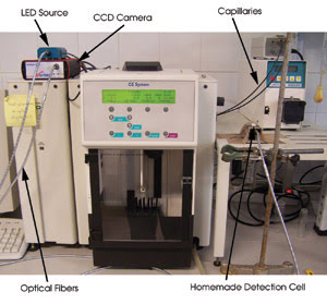
Figure 3. To test the ability of fiber optic-linked LEDs to replace
lasers for exciting fluorescence during capillary electrophoresis, researchers at
the University of Granada in Spain used a pulsed light source outfitted with an
LED that emits at 470 nm, a bifurcated fiber optic probe and a spectrometer with
a linear-array CCD detection chip with 2048 pixels. Courtesy of Antonio Segura-Carretero.
The design of the detection cell enabled
the investigators to adjust the distance between the end of the fiber and the outer
edge of the capillary, and they found that the narrower the gap, the higher the
sensitivity: At a distance of 2 mm, the limit of detection was 28 μM; at 0.05
mm, it was 2.6 μM.
In tests involving various naturally
fluorescent, nonfluorescent and fluorescently tagged compounds, the researchers
found that the system provided adequate detection capability, albeit with detection
limits not as low as can be achieved with laser-induced fluorescence. They believe
that the detection limitations of the LED-based system can be improved by using
LEDs brighter than the 50-μW device that they used, a more sensitive CCD detector
chip, a more efficient fiber optic or a combination of the three.
Sample preconcentration
Among the techniques that have been developed
to improve capillary electrophoresis are field-amplified stacking injection (FASI)
and microfluidics.
In FASI, water or another low-conductivity
solution is introduced into a buffer-filled capillary, followed by some amount of
sample solution. When a reverse-polarity electric field is applied to the capillary,
the analyte’s anions accumulate, or stack, at the boundary between the buffer
and the sample solution while the plug of water is pumped out of the capillary entirely
by the electro-osmotic flow. Stacking the ions in this manner concentrates the analyte
ions as they pass the detector, increasing the sensitivity of measurements without
significantly losing resolution.
Shrinking capillary electrophoresis
experiments to the microfluidic scale reduces sample amounts, processing time and,
ultimately, costs. However, performing experiments on a microchip — especially
when trying to integrate FASI techniques — is complicated by the open system
of valveless channels that are used in place of a single capillary.
Now, Maojun Gong, William R. Heineman
and Patrick A. Limbach of the University of Cincinnati’s department of chemistry,
and Kenneth R. Wehmeyer and Francisco Arias of Procter & Gamble Pharmaceuticals
in Mason, Ohio, have described a method to bring FASI to microchip capillary electrophoresis.
They report in the June 1 issue of
Analytical Chemistry that they used the simplest possible microchannel design
— a regular cross in which four channels meet at an intersection at 90°
— to demonstrate that the common variations in velocity within the bulk solution
could be used to facilitate the FASI technique.

Figure 4. To demonstrate the feasibility
of field-amplified stacking injection in a microfluidic chip, investigators took
advantage of the mismatched flows of buffer and sample within a simple, cross-shaped
system. By manipulating the voltage configuration among the four points of the cross,
they loaded sample solution system (A), created sample buffer plugs (B), stacked
analyte ions along the boundaries between low- and high-concentration buffers that
accumulate in the long arm (C), and positioned the stacked ions at the point of
detection (D). Courtesy of the American Chemical Society.
At the ends of channels etched into
a cruciform upon a glass chip, the researchers attached reservoirs to hold the sample,
the buffer and the waste from each (Figure 4). An applied voltage across the short
arm of the cross pumped low-conductivity sample solution from its reservoir through
the intersection and into its designated waste receptacle. To inject a low-conductivity
sample buffer plug into the separation channel to serve as the FASI medium, they
switched the voltage to run between the sample reservoir and the buffer waste receptacle.
This drove the sample into all of the channels except the separation channel, in
which only a low-conductivity sample buffer plug was introduced, while the anionic
analytes were filtered out by the high electric field there.
According to Gong, who led the experiment,
in a traditional sealed capillary, the velocity of the bulk fluid is the average
of the faster moving low-conductivity material and the slower high-conductivity
solution. In the open channels of a microchip, the high-conductivity material has
more freedom to move, and it acts to induce solution flow within the branches, enabling
the next step.
To stack the ions, the investigators
reversed the polarity of the prior step, applying a voltage between the sample and
buffer waste receptacles. This caused the bulk fluid to flow toward the sample waste
receptacle from each of the channels, through the intersection. During this migration,
the analyte’s anions accumulated at the boundary between the low- and high-conductivity
solutions.
Just before the backward-running plugs
reached the intersection, Gong switched the voltage again, turning the plug away
from the intersection. This separated the stacked analyte ions into zones that then
passed by a detection system composed of a photomultiplier tube from Hamamatsu Corp.
of Bridgewater, N.J., a CCD camera from Dage-MTI Inc. of Michigan City, Ind., an
inverted microscope from Nikon Corp. of Melville, N.Y., and a 150-W xenon flashlamp
emitting at ~480 nm. They used neutral and anionic fluorescent dyes to image
the FASI process inside the chip (Figure 5).
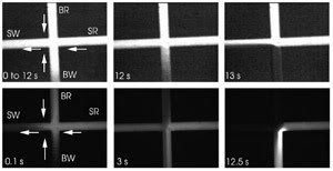
Figure 5. Separately using two fluorophores (A, B), the researchers
imaged the field-amplified stacking injection process depicted in Figure 4C. The
arrows indicate the bulk flow direction. SW = sample waste, SR = sample reservoir,
BW = buffer waste, BR = buffer reservoir. Courtesy of the American Chemical Society.
The researchers found that the length
of the sample buffer plug influenced the level of detection enhancement that they
could achieve. By varying the duration of the plug-injection step, they manipulated
the plug length. If the plug was too short or too long, signal enhancement was reduced;
ultimately, they found that an injection time of 15 s was optimal. In experiments
with fluorescein-5-isothiocyanate, fluorescein disodium salt and 5-carboxyfluorescein,
they recorded detection enhancements of 94-, 108- and 160-fold, respectively, relative
to the commonly used pinch injection method.
They note that the technique, thus
far, works only with anions, but that minor modifications would enable the detection
of cationic analytes as well. Gong also said that there would be value in testing
the technique in more complex microchip designs, because advanced chips have additional
channels that enable such processes as mixing and chemical reactions.
Coating capillaries
No matter how successfully you shrink a capillary
system or optimize the sample concentration, analyzing proteins via electrophoresis
is problematic: Because of ionic interactions, hydrogen bonding and van der Waals
interactions between the sample and the glass or fused-silica material, proteins
tend to adhere to the inside wall of the capillary or microchannel, extending the
sample volume and thereby reducing sensitivity.
Coating capillaries to make them less
prone to protein adsorption is common, but existing coatings do not fulfill the
three main requirements for optimizing capillary electrophoresis: high resistance
to protein adsorption, the ability to limit electro-osmotic flow, and high stability,
which is necessary for compatibility with online mass spectrometry techniques.
At West Virginia University in Morgantown,
Aaron T. Timperman and his colleagues have developed a coating composed of polyethylene
glycol (PEG) and silane that addresses each of these requirements.
The researchers report in the July
1 issue of Analytical Chemistry that they used PEG because it provides excellent
resistance to protein adhesion. To investigate the optimal combination of PEG and
silane, they formed two coatings: one composed of silane terminated with a PEG with
a molecular weight of 750, and another with a molecular weight of 4000 to 5000.
They also concocted a third coating, composed of a mixture of the first two.
Using a capillary electrophoresis system
from Beckman-Coulter Inc. of Fullerton, Calif., featuring a 488-nm argon-ion laser
for fluorescence excitation and a photodiode array for detection, the scientists
tested the coatings on fused-silica capillaries. They also tested them on a glass
microfluidic chip.
After the coating step, they exposed
the channels and capillaries to various proteins — bovine serum albumin, for
example — that were tagged with fluorescein isothiocyanate. They then measured
the fluorescence intensity of the adsorbed protein-fluorophore compounds using an
inverted microscope from Nikon, a 4x objective, a 530 ±30-nm emission bandpass
filter and a CCD camera from Roper Scientific in Tucson, Ariz.
They found that the coatings composed
of the larger PEG molecules and those composed of a mixture of large and small PEG
particles most efficiently reduced electro-osmotic flow, suppressing it by >90
percent. Using short PEG molecules alone achieved 65 percent reduction in electro-osmotic
flow.
The coatings were stable, with those
on the glass microchannels dropping in efficiency to an equivalent flow reduction
of ~84 percent after about 30 runs. Coatings on the fused-silica capillaries
lasted for more than 200 runs, with the flow reduction dropping to 78 percent.
According to Timperman, the characteristics
of the coatings, especially their stability over a large number of runs, makes them
suitable for mass spectrometry, and his group foresees testing them in combined
capillary electrophoresis/mass spectrometry experiments.
“Using capillary electrophoresis
with ultraviolet or other types of optical detection will provide quantitation,”
he said, “while mass spectrometry will provide the characterization.