Gert Noll, TEC5USA Inc., and Mathias Holzapfel, TEC5 AG
Good wavelength accuracy and high sensitivity are key optical features of a spectrometer system, although resolution is a matter of mechanical design. However, in process control, the detector array and the related readout electronics are often more crucial for a successful application, and a large signal-to-noise ratio and a high dynamic range are sought-after features. Moreover, monitoring fast processes, such as a pulsed solar simulator, requires operating electronics with precise timing.
When spectrometers were touchy instruments confined to laboratories, the features that mattered were the spectral range and resolution that the device could obtain without sacrificing sensitivity. Timing did not matter because the single-element detectors showed momentary values only. The overall readout times were measured in minutes rather than seconds – or even less. The grating or prism moved slowly to scan a wavelength range, and users hoped the spectrum did not change drastically over time so that the final signal represented the same status as the initial values.
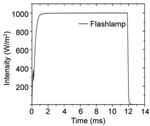
Time distribution of a pulsed solar simulator. Courtesy of Tec5USA Inc. (Figure 1).
With the advent of detector arrays, the whole picture changed: There was no worry about slow-moving dispersive elements anymore; a spectrum could be captured in milliseconds.
As long as the spectrometer readout is not electronically linked to any process, the timing is in the hands of the operator, to hit the key when the time is ripe. Subsecond exposure times opened the door to a whole new world: the spectral monitoring of fast processes. Faster measurement allows acquisition of more samples, so it provides more accurate in-line information. Processes such as film coatings could be controlled with much greater precision, showing how important time and timing are.
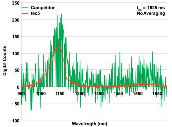
Comparison of spectrometer electronics quality: same event recorded with the same detector array and parameters but different electronics. Courtesy of Tec5USA Inc.
Part 1: Detector-Array Electronics
Modern process-control demands
The most important feature of a spectrometer is that it covers the spectral region of interest. Often, the demand for resolution is mixed up with the demand for accuracy. For example, if measuring the slope of a transmission filter determines the cutoff wavelength, there is little to discriminate between two wavelengths – but it is important that the slope is always measured at exactly the same wavelength. Resolution often must be sacrificed over sensitivity, because a fast measurement can be accurate with respect to intensity only if enough light is hitting the detector, and the shorter measurement times allow less light to hit the detector. A larger bandwidth per pixel, however, leads to more light per pixel. Thus, the signal measured by each pixel is higher, but the consequence is lower spectral resolution. Therefore, a high sensitivity is the first demand for fast measurements.
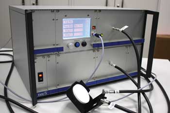
A system with spectrometer, trigger electronics and the (outside) detector surface to tap the flash for trigger-signal generation. Courtesy of Tec5USA Inc.
Without the millisecond readout of an array, no fast processes can be observed or controlled. Therefore, the second demand is to measure quickly, which almost seems to be a trivial statement.
To achieve a large dynamic range – the capability to measure small and large signals – the detector needs a high-well capacity, and the electronics and the analog-to-digital converter that match it. The combination of detector and electronics also needs a good readout quality with low noise. At 16-bit conversion, a readout noise of 1.5 counts rms results in a dynamic range of more than 40,000 (highest divided by lowest signal measurable).
Some spectrometer systems give the impression that although spectrometers can be read out in milliseconds, exact timing – at what precise time a spectrometer is read – does not really matter. Solar simulator monitoring shows that timing does matter and that it is crucial to the quality of a measurement.
Background: Timing, accuracy
To measure light intensity accurately, the time period over which the light is collected must be precisely controlled. The readout time directly influences the amount of measured signal: If the readout time is 1 percent too long, then 1 percent too much light is detected.
One timing aspect in a process environment is the reaction time from synchronization to external events. Typically, these events send a trigger signal, and the measurement system must react on this event within a specified time.
This reaction time depends only on the electronics and its implemented work mode. In nontriggered environments, the electronics operates the detector array in a free-running mode, where the sensor is read out in time intervals based on the integration time. To view a spectrum, an operator can send a software request. If the electronics is reading out the sensor at the time of the request, then it finishes the data acquisition before it records the next spectrum.
In a standard triggered mode, the software request is replaced by the trigger event. As with the free-running mode, it could take up to one integration period until the spectrum of the sample requested by the trigger event can be recorded. The delay is that long if the detector array electronics is busy with a readout cycle. Such a delay may be several milliseconds, which is not acceptable in many situations. For example, a sample on a conveyor belt might have passed already, or the state of a technical process may have altered within this delay time. Furthermore, a jitter would appear if the samples were not passing by regularly or if the monitored event had no exact time reference to the recording period. In such a case, a different detector-array work mode is required. Rather than wait for the next integration cycle, the electronics interrupts the acquisition immediately after receiving the trigger signal and starts a new scan. This minimizes the delay to a few micro seconds.
Another issue can be the readout rate. On the millisecond timescale, the spectral acquisition of silicon detector arrays is not a simultaneous process. Often, the pixels of a detector array are read out one after the other so that each pixel represents a slightly different time period. The last pixel contains information from a complete scan time – a couple of milliseconds – later. This effect can be minimized only by a high readout frequency (clock rate) of the detector chip, a generally important design goal.
A 1-MHz clock frequency is about the highest frequency suitable for high accuracy, and the overall readout time is about 1 µs (treadout = Npixel/fclk). For silicon PDAs and CCDs, the readout time normally represents the shortest exposure or integration time. To achieve an accuracy of 0.1 percent (about 10 bits), the timing accuracy must be 1 ms/1000, or about 1 µs. However, to reach 16-bit accuracy, the timing must be precise to 15 ns. Therefore, a good analog-to-digital converter must be accompanied by an exact timer for the integration time control. The downside to a higher frequency is a lower quality of the signal readout. The engineering goal is to find the most suitable compromise.
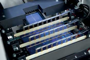
Detailed view of solar cell test station. Courtesy of ASYS Solar.
Part 2: Solar Simulator Monitoring
Pulsed events
A typical modern application is the monitoring of solar simulators, often called “flashers.” The flashers emit millisecond light pulses that spectrally mimic the light generated by the sun. The simulated sun helps to characterize solar cells in a neutral, reproducible way. This application is very demanding because of the required precise triggering and fast data acquisition. The emitted spectra vary not only from flash to flash, but also over the duration of each flash. Thus, a fast readout is essential: More spectra can be taken across the time axis of a flash if the acquisition times are short, representing a high time resolution.
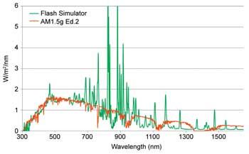
Comparison of the spectral outputs of a solar simulator based on flashlamps and the standardized emission spectrum of the sun as found on Earth. Courtesy of Tec5USA Inc.
Figure 1 shows a typical time distribution of a solar simulator pulse. The efficiency of solar cells or modules is measured during the equilibrium phase of this light pulse, because that is when the emitted light spectrum is stable. During the rising and falling edge, the flash spectrum is rapidly changing. Thus, it is important to measure the spectrum at a precise time after the flash has started.
Measuring at the right time on the equilibrium phase needs a precise trigger event. To achieve independency of the flasher electronics, it is best to use the flash itself. This requires the implementation of a separate single-element photodiode detector to detect the light.
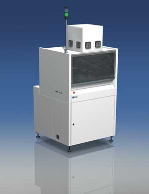
Flasher in a solar test handling system. Courtesy of ASYS Solar.
Because the spectrometer is still sensitive during the idle phase, a signal from ambient light and dark current accumulates on the detector over time. This signal would affect the flash spectrum, so the spectrometer detector is first cleaned by a readout of the array without recording the spectrum. This cleaning requires a special detector-array work mode. (Modern electronics allows implementation of new work modes by uploading firmware.)
Timing of wide-range systems
Recording the full flash spectrum over a wide spectral range requires multiple spectrometer units, each equipped with a different sensor technology for the various spectral ranges. Silicon-based detector chips are sensitive from the ultraviolet up to about 1 µm, while InGaAs detectors detect light above 1 µm. Combining the two detectors is a challenging application that requires exact timing information for both sensor arrays involved.
Unfortunately, both detector types have different readout principles: Although a Si-based detector is sensitive all the time, an InGaAs detector is sensitive only during the exposure phase. The latter is not sensitive during the readout phase, which lasts about 1 ms, if readout frequency is high. This supports the request for a high readout frequency.
If both sensors have to collect light over the same equilibrium-phase period, they both must be triggered at different time positions. To compensate for the “blind” phase, the near-IR spectrometer unit must be triggered about 1 ms, or exactly the readout time of the used chip, which is earlier than the Si detector should be triggered. Also, the cleaning timing differs with various sensor technologies.
To prepare the flash emission determination described above, a so-called “burst” mode acquires spectra across the complete flash time period as quickly as possible. A burst is a defined number of spectra recorded one after the other without any additional delay. These spectra provide information of the various time zones of the flash: Plotting a single wavelength over time reveals the envelope of the flash intensity over the time axis.
A good signal-to-noise ratio is required for a high-accuracy measurement. Acquiring as many spectra as possible during the whole equilibrium phase is highly recommended so that the signal quality can be improved by averaging. However, the acquisition window should exclude the rising or falling edge of the pulse to avoid a deformation of the spectral information.
To monitor fast processes, detector arrays must be operated at fast readout rates; short integration times require timing accuracy in the nanosecond range. A flasher monitor needs a delay functionality to confine the spectral measurement to the equilibrium phase only, and timing must be carefully controlled to account for different cleaning and delay times for the sensor technologies involved. Various work modes must be implemented to match the performance of the spectrometer system precisely to the multifold task.
Meet the author
Dr. Gert Noll is general manager at Tec5USA Inc. in Plainview, N.Y.; email: gert.noll@ tec5usa.com; Mathias Holzapfel is product manager at TEC5 AG in Oberursel, Germany; email: [email protected].