Matt Kirchner, Allen Hankla and Chris Wood, Kapteyn-Murnane
Easy group delay dispersion measurements improve results in applications such as laser amplifiers, optical coatings, harmonic generation, bioimaging and microscopy.
“Dude, where’s my pulse width?!”
Anybody working with an ultrafast laser has probably uttered these (or similar) words at some point. Symptoms of pulse width problems can come in the form of lower conversion efficiencies, fainter microscope images or lower signal-to-noise ratio (SNR) for a given experiment.
Imagine you are the proud new owner of an ultrafast laser system. The laser is delivered, specs are successfully demonstrated, and you have routed the output beam through 10 or so optics to your experiment – only to find that you are not getting the SNR you expected. Tweaking the laser doesn’t help; tweaking the experiment doesn’t help, so it must be something in between: The routing mirrors? But which one? In other words, how can you be sure that what came out of the laser is what hits your experimental sample?
For optimal results, broadband applications such as coating test and validation, ultrafast laser systems and beam delivery, high harmonic generation, ultrafast microscopy, micromachining and imaging rely on accurate knowledge and control of each wavelength’s relative phase. For ~500-fs pulses, knowing the effects on phase of bulk optics such as laser rods and prisms is sufficient; however, for pulses on the order of 100 fs or less, the phase contributions from mirrors and lenses become increasingly important as the pulse width gets shorter.
Until now, users have had to rely on theoretical coating curves (which can differ significantly from actual coating runs because of manufacturing errors1), home-brew instruments or system-level measurement equipment to quantify these effects. But now, using a white-light interferometer (WLI) to measure group delay dispersion (GDD) has become much easier, giving users of ultrafast laser systems, beam delivery optics and optical coatings assurance of optimal ultrafast laser performance and experimental results.
Why does GDD matter?
To get the absolute shortest pulse out of a laser system, the relative phase of every wavelength must be lined up and accounted for. Various wavelengths have different phases because the index of refraction of every optical component, from laser rod to mirrors to air, varies with wavelength. This variation in index is called dispersion and results in an arrival delay of the wavelength group (hence the term group delay). In real materials, because this group delay varies with wavelength, the variation is called group delay dispersion (see Equation 1).
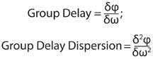
Equation 1. φ is the phase, and ω is the angular frequency of the photon.
Knowing the GDD of all the optics in an experiment lets you compensate for it, resulting in clean, short pulses that increase the SNR for most experiments.
The GDD of bulk optics can be accurately calculated using the Sellmeier equations, but calculating the GDD of coated optics can be tricky. Figure 1 shows a perfectly compressed (transform limited) ultrafast pulse, along with the underlying electric field and its pulse envelope. It is the amplitude and phase of the spectral components of the pulse that will determine the final pulse width. Because of the bandwidth of a femtosecond pulse, the spread in wavelengths is significant, and various wavelengths penetrate the optical coating to different depths – or traverse a different number of coating layers.
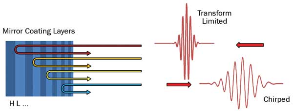
Figure 1. This schematic illustrates dispersion in coated optics and its effect on ultrafast pulses. H = high-index layer, L = low-index layer. The ... indicates that the layers continue to alternate between high and low index.
Figure 5. Using the Chromatis white-light interferometer, a coating manufacturer improved its group display dispersion (GDD) specification from 4100 fs2 to 50 fs2 for a mirror over the wavelength range of 1020 to 1050 nm. In all coating runs, the transmission and reflection specifications were met.
The resulting reflected pulse then has an accumulated wavelength-dependent phase that alters the underlying electric field. In this case, the reflected pulse is chirped, showing that the short wavelengths arrive first and the longer wavelengths later. This can be a highly detrimental effect, or it can be tailored to great benefit. In either case, though, it is important to be able to measure the effect.
GDD measurement theory
There are two primary techniques for measuring GDD, and both use a WLI:time domain3 and spectral domain4; we will focus on the time-domain WLI because it has several distinct advantages over the spectral-domain WLI, as outlined below:
• An inexpensive single-element photodiode detector can be used instead of a spectrometer detector array, enabling quick changes from the visible to the near-IR or other wavelength ranges, depending on the optics under test.
• The HeNe reference laser provides a built-in calibration of the wavelength axis for each scan; the wavelength axis of spectrometers can drift with time and temperature, and, therefore, the wavelength axis of a time-domain WLI is more accurate than a spectral-domain WLI.
• Measuring different polarizations simultaneously is simply a matter of adding a polarizing beamsplitter and a photodetector rather than having to purchase a separate spectrometer or repeat the measurement for each polarization.
• For low-light levels where the signal is dominated by detector noise, there is an SNR advantage (Fellgett’s advantage2) to using a single detector rather than a detector array.
A broadband, temporally incoherent light source (e.g., a halogen bulb) is collimated and sent through an interferometer consisting of a broadband beamsplitter and two delay arms. One arm (the reference arm) uses a low-dispersion mirror, while the other (the test arm) contains the test mirror. In a similar way, a WLI also can measure the dispersion of a transmissive sample by replacing the test mirror with a low-dispersion mirror and placing the transmissive sample in the beam path.
The time delay (Δt) between the two arms is scanned across Δt = 0. In the regions around Δt = 0, the white light signals from each arm interfere with each other, giving an interference pattern that is detected by a photodiode and recorded by a computer.3 A coherent source (HeNe laser) is co-propagated with the white light to serve as a precise distance reference for the time-delay scan. The HeNe fringes are recorded on a separate photodiode.
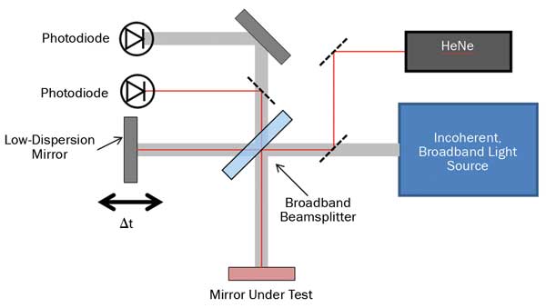
Figure 2. A schematic of a white-light interferometer.
The white-light interference pattern contains information about the relative phases of the light from the test arm and the reference arm. A computer is used to process the interference pattern and extract the phase and dispersion properties of the mirror under test using the relationships in Equation 1. This method of dispersion measurement is very versatile because only a single element detector is needed for the white-light measurement, and automatic wavelength calibration is assured using the HeNe optical reference. This means that a dispersion measurement can be made at any wavelength where a broad bandwidth source and a detector are available. In addition, an increase in real resolution is obtained by scanning over a longer delay.
There are some practical limitations to this measurement. If the white-light source is fiber-delivered to simplify the setup, some wavelength range limitations arise. In addition, real-world measurement issues such as amplifier noise, light noise and digitization noise put a limit on the amount of time delay that can be scanned before the integrated noise becomes greater than the signal (limiting the resolution). At moderate resolutions (5 nm is ideal for most ultrafast optics), both the absolute and relative noise are low, and standard deviations of <5 fs2 are typical over most of the measurement range for only a few averages.
GDD measurement practice
Historically, GDD measurements have not been widespread because the instruments were home-built, required Ph.D.-level expertise to use and were not very user-friendly.4 This was the case initially at KMLabs, where we must know very precisely the GDD of every critical optic in our systems. But we soon realized that there was a wider demand for these measurements, and that, by making them readily available, we could expect rapid improvements in the coating technology used by our suppliers.
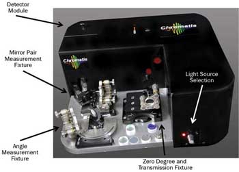
Figure 3. The Chromatis white-light interferometer, showing the user/measurement area and fixture storage area.
We engineered the Chromatis white-light interferometer (Figure 3) to enable quick, accurate measurements on almost all of our optics:
• GDD resolution: ±5 fs2.
• Measures both polarizations simultaneously.
• HeNe reference laser for automated wavelength self-calibration of every measurement.
• Standard design for 1-in.-diameter optics, highly repeatable fixtures and optomechanical referencing.
• Four standard measurement modes with precision fixtures:
• 0° angle of incidence (AOI) in reflection
• 5° to 70° AOI in reflection
• 0° to 70° AOI in transmission
• Mirror pair measurement with variable AOI (6° to 54°)
• Reference optics for reflection and transmission modes of operation.
• Two detector modules available:
1. Si: 500 to 1100 nm
2. InGaAs: 1000 to 1650 nm
A NIST-style round-robin competition has confirmed the accuracy of this device against spectral-domain WLIs at three other companies. Figure 4 illustrates sample data taken with 500- and 750-fs time-delay scans alongside a spectral-domain WLI owned by Laseroptik GmbH, showing excellent agreement over the central 400-nm range.
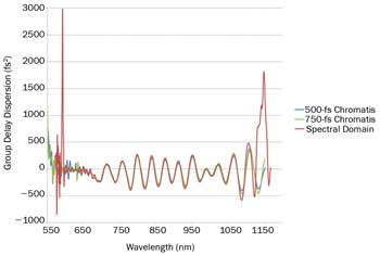
Figure 4. Validation of Chromatis using a well-known spectral-domain white-light interferometer at Laseroptik GmbH.
Effects of improvements
As with any measurement, once user-friendly instruments are made accessible to a wide group of users, rapid improvements in the technology can be expected; e.g., one coating manufacturer has used the Chromatis to dial in its measured GDD on a 1030-nm mirror.
Figure 5 shows the evolution of the measured GDD compared with the goal for three coating runs. To compensate for positive GDD caused by the laser system, the GDD goal for this mirror was a constant −1200 fs2 over a wavelength range of 1020 to 1050 nm. In each coating run, the reflection and transmission specifications were met, but the initial coating run resulted in a maximum GDD deviation of 4100 fs2 from the goal; the second coating run reduced the margin to 1400 fs2, and the final run was within 50 fs2.
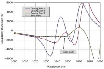
Figure 5. Using the Chromatis white-light interferometer, a coating manufacturer improved its group display dispersion (GDD) specification from 4100 fs2 to 50 fs2 for a mirror over the wavelength range of 1020 to 1050 nm. In all coating runs, the transmission and reflection specifications were met.
The improvement in GDD for this one mirror is significant, as illustrated in Figure 6a: After hitting the mirror made with the first coating run, a transform-limited 100-fs pulse would suffer a 5 percent decrease in peak intensity, although it would lose only 0.1 percent in peak intensity after hitting a mirror coated in the third run. For many laser systems, there can be a significant number of mirrors, and the effect of their GDDs is cumulative; this can be the case for multiple round-trips in an oscillator, a beam path within an amplifier, or a long route between the laser output and the experiment.
Figure 6b illustrates the effects of 10 bounces from the same mirror for each of the three coating runs: Run 1 results in multiple pulses spread out over more than a picosecond with only 24 percent of the initial peak intensity, while Run 3 maintains 98.4 percent of the initial peak intensity.
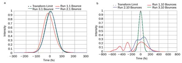
Figure 6. Calculated pulse shapes after reflection from a mirror with the same coatings illustrated in Figure 5. The incident pulse is 100 fs full width half maximum and transform-limited. (a) The pulse after a single reflection from the mirror with GDD in coating Run 1 with 4100-fs2 maximum GDD error, coating Run 2 with 1400-fs2 maximum GDD error, and coating Run 3 with 50-fs2 maximum GDD error; (b) the same pulse after 10 bounces from mirrors with coating Runs 1, 2 and 3. Note the different timescales for (a) vs. (b). After 10 reflections from a mirror with Coating Run 1, the peak intensity is reduced to 24 percent of the original intensity as compared with 98.4 percent for coating Run 3.
This peak-intensity reduction can have even more dramatic effects in experiments reliant on two-photon processes such as frequency doubling and microscopy, where the desired signal is proportional to the intensity squared; it also gets more pronounced as the incident pulse width gets shorter.
Now everyone can have the capability to quickly and easily measure the dispersion of optics. Coating manufacturers can refine processes, ultrafast laser manufacturers can build better laser systems, and ultrafast laser users can optimize their experiments for better results.
Meet the authors
Dr. Matt Kirchner is a laser scientist at Kapteyn-Murnane Laboratories; email: [email protected]. Allen Hankla is a laser consultant at Kapteyn-Murnane Laboratories, and Dr. Chris Wood is the chief technology officer.
Acknowledgment
The authors would like to thank LaserOptik GmbH for allowing us to share its white-light interferometer data.
References
1. M.K. Trubetskov et al (2013). Measurements of the group delay and the group delay dispersion with resonance scanning
interferometer. Opt Express, Vol. 21, Issue 6, pp. 6658-6669.
2. P.B. Fellgett (1949). On the ultimate sensitivity and practical performance of radiation detectors. JOSA, Vol. 39, Issue 11, pp. 970-976.
3. Scott Diddams and Jean-Claude Diels (1996). Dispersion measurements with white-light interferometry. JOSA B, Vol. 13, Issue 6, pp. 1120-1129.
4. A.P. Kovács (1995). Group-delay measurement on laser mirrors by spectrally resolved white-light interferometry. Opt Lett, Vol. 20, Issue 7, pp. 788-790.