John Wingerd, Siskiyou Corporation
Optical mounts literally form the skeleton of virtually all laser systems. The development of mounts with greater stability and wavefront fidelity is key to the creation of higher-performance laser-based tools. This, in turn, extends the precision and reliability of a wide range of manufacturing systems and instruments.
Optical mounts frequently play a critical role in overall laser system performance, but their impact may become obvious only when optical misalignment from vibration, thermal drift or long-term mechanical creep causes system operation to degrade.
In this article, we will review basic styles of optical mount design and construction, and compare various mount types in terms of stability, functionality and cost. We also will explain the impact of various component-mounting techniques on wavefront distortion, and present recent test data on a new type of flexure mount designed for high thermal stability. The design provides the beam-pointing stability and component economy that increasingly are needed in demanding OEM industrial and scientific laser-based applications.
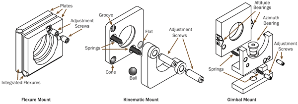
Figure 1. Basic construction of different types of optical mounts.
There is an ongoing trend in manufacturing across numerous industries for both greater precision and reduced cost. In microelectronics, this stems from the move toward packaged circuitry, which squeezes ever-greater functionality into a small form factor at market-enabling prices. In the display industry, it results from the push for brighter, higher-resolution displays with lower power consumption for televisions, tablet devices and cellphones. In the automotive industry, it helps empower the relentless drive toward greater fuel efficiency and reduced maintenance.
Higher performance requirements
Lasers support much of this high-precision advanced manufacturing. For example, they drill small holes in circuits to enable highly miniaturized, advanced circuit packages, and they cut difficult-to-machine, strengthened glass for touch-screen displays. Increasing precision in these applications translates directly into a need for improved performance in the optical mounts used in laser-based manufacturing systems.
Lasers are also being increasingly employed in high-precision instrumentation, particularly in the area of life sciences. Specifically, laser-excited fluorescence detection techniques are at the heart of numerous biomedical instruments, including flow cytometers used for performing blood tests, confocal and multiphoton microscopes for research, and lab systems for DNA sequencing.
But what exactly does “improved performance” in these myriad applications mean in terms of optical mounts? Most importantly, it manifests as greater long-term pointing stability, especially in the presence of ambient temperature variations, and mechanical shock and vibration. This is critical because beam wander degrades system alignment, usually resulting in a drop in power, an increase in spot size or physical displacement of the final focused laser spot, all of which can negatively impact the laser-based process and detection schemes. Beam wander also impacts cost of ownership for the end user, because it may necessitate system downtime for realignment or a service call from the manufacturer.
Improved performance can also mean better methods for holding the optic. That’s because sophisticated laser systems often use high-performance optics with very high accuracy surfaces (typically, quarter-wave surface accuracy or substantially better). However, the mechanical stress of holding the optic in the mount can easily warp a component out of this shape. This must be minimized in many cutting-edge applications today.
Mount construction
Optical mounts commonly offer adjustment in two degrees of freedom (θX and θY, with Z being the optical axis) and can be broadly classed by their basic design into three categories: kinematic, flexure and gimbal. For purposes of this discussion, it’s also useful to limit ourselves to “OEM” mounts – that is, mounts specifically optimized to be built into equipment, as opposed to “lab” mounts, which are intended for frequent adjustment in the research setting. In OEM mounts, operational flexibility is generally not a priority; thermal stability, mechanical stability and cost are paramount.
Because of these considerations, OEM mounts typically use fine-pitched screws, rather than micrometers, for adjustment. These mounts usually are located inside an instrument, so a small overall footprint may also be important. The ability to perform all adjustments from either the top or a specific side may also be desirable.
Kinematic mounts typically use a “cone, groove and flat” arrangement: A steel ball rests within a cone at the corner of two flat plates that are connected with springs. The ball acts as a pivot point and prevents sideways motion. A spherically tipped actuator pushes into a groove providing θX (tip) adjustment, while a second spherically tipped actuator pushes against a flat to deliver θY (tilt) movement. However, these motions are not truly orthogonal and also do not occur around the front surface of the component. Thus, adjusting a mirror always produces some translation of a beam, in addition to angular movement.
Kinematic mounts are a well-established, reliable technology and are available over a wide spread of price/performance characteristics. They can be designed to offer a large adjustment range, and the springs can be load-rated so they are optimized for the weight of a specific optic.
Because a kinematic mount is composed of several small pieces, tolerances can combine so that the resulting assembly has mechanical “play,” meaning that unwanted motions can occur during adjustment. Play also degrades the long-term stability of the mount, especially when exposed to vibration. Corner bearings can even fall out when the adjustment screws are overdriven. Furthermore, the minimal mechanical contact between the individual plates doesn’t provide a good way for heat to flow through the part, degrading thermal stability.
Early flexure mount designs use pairs of plates connected by stiff leaf springs (flexures). To achieve two-axis motion, three plates are used with the flexures at right angles to each other. Leaf springs typically limit the adjustment to a smaller angular range than that of kinematic mounts. As with kinematic mounts, the center of rotation in a flexure mount is not at the front surface of the optic, and the motions are not truly orthogonal.
The stiffer springs used in these early flexure mounts, together with slightly greater thermal contact between the individual plates, generally make them more stable than kinematic mounts in the presence of vibration, mechanical shock and thermal variations. They also render flexure mounts mechanically compact and nearly impossible to overdrive.
To enable easier access, adjustment screws are often located on the top, rather than the back, of the mount assembly in space-constrained laser-based instruments. Both kinematic and flexure mounts can be configured for top adjustment. However, this increases mount complexity. In kinematic mounts, which already contain numerous parts, this raises the potential for backlash and makes the mount less thermally and mechanically stable. In contrast, this configuration doesn’t significantly degrade the performance of flexure mounts because of their inherent simplicity and stiffness.
The main distinguishing feature of a gimbal mount is functional, rather than constructional. Specifically, gimbal mounts place the center of rotation at the front surface of the optic. This means that rotational adjustments do not result in any unwanted beam translation, which could cause a change in beam path length. Furthermore, gimbal mounts are the only ones to offer truly orthogonal motion. Gimbal mount designs generally bear most of their weight on a bearing, rather than suspending the optic on a spring, resulting in a high load-bearing capacity. For all these reasons, they are usually the first choice for mounting very large components. Gimbal mounts can also be designed to provide full 360° orientation in both axes.
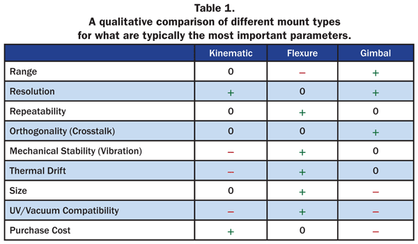
The primary negative of gimbal mounts is their higher mechanical complexity. This makes them generally more costly than either flexure or kinematic mounts. It also leads to the same problems with thermal and mechanical stability as experienced with kinematic mounts. The relative merits of each mount type are summarized in Table 1.
Next-gen OEM mounts
Clearly, flexure mounts offer a favorable combination of performance, size and cost characteristics, making them a common choice for OEM systems builders. However, there are some specific design and construction techniques that can substantially improve their performance advantages.
An important recent innovation in flexure-mount technology is the development of next-generation products with monolithic construction. Traditional two-axis flexure mounts consist of three separate plates attached to two individual leaf springs using screws or spot welding. By contrast, the monolithic mount is machined entirely from a single piece of metal – both plates and springs are integral to flexure-mount geometry. This construction confers two important advantages.
The first benefit is improved heat transfer through the entire mount. Because the mounting surfaces and spring members are integrated into a one-piece monolithic design, the entire assembly expands or contracts uniformly with temperature changes. This is not true of a traditional flexure mount, where different spring and plate materials expand at different rates, resulting in changes in pointing stability.
Figure 2 shows the differences in thermal expansion characteristics for three commercially available mounts. Specifically, it graphs the deflection as a function of temperature for a monolithic flexure mount, along with two kinematic mounts specifically marketed as having enhanced thermal stability. The monolithic mount demonstrates performance that is at least three times better.
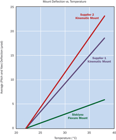
Figure 2. Thermal stability (averaged over both X and Y axes) for a Siskiyou IXF1.0i monolithic flexure mount, compared with ‘high stability’ kinematic mounts from two other manufacturers. Thermal performance data for the latter two comes from manufacturers’ published literature.
Another significant advantage of monolithic construction is enhanced vacuum compatibility. In mounts constructed from numerous diverse parts, gas can be trapped in various areas of the assembly, so these “blind holes” must be drilled through to allow gases to escape. In a monolithic design, there are no blind holes. Heat flow is difficult in a vacuum – there’s no air to conduct the heat. Monolithic designs offer a path for heat to follow as it travels, minimizing the effect of hot spots.
In addition to degrading vacuum compatibility, this elevated possibility for outgassing can be further problematic in systems based on ultraviolet lasers. This is because UV optics are particularly sensitive to any material that gets deposited on their surfaces. Any outgassed material can lower optics transmission or mirror reflectivity, and also acts as a catalyst for laser damage.
The main disadvantage of this advanced design is increased cost, especially compared with some lower-priced kinematic mounts. However, for the customer, the increased system purchase price for employing monolithic flexures may be offset by reduced need for costly field service.
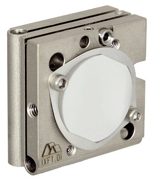
Figure 3. This optics mounting clip is designed to provide secure mounting with minimal part distortion.
Stress-free mounting
Optical components are typically held in a mount either by adhesive or some mechanical means. The advantage of mechanical retention over adhesives is that a component can easily be removed for cleaning or replacement. Plus, adhesives can shrink and increase stress during curing. A mechanical retaining method should satisfy two imperatives. First, it should hold the optic securely enough so that it can’t move around in the mount (particularly for a radiused component, where lateral movement can affect beam alignment). Second, the retaining method should minimize any mechanical stress that would deform the optic, because this degrades wavefront performance.
The most common method for retaining an optic is a set screw that impinges radially on the edge of the component. This method is simple, cheap and effective. Unfortunately, the single-point side contact also deforms the optic.
Various manufacturers have developed their own alternative methods for retaining components without inducing mechanical stress. A patent-pending method by Siskiyou consists of a thin plate that covers the edge of the component on two sides and then attaches to the face of the mount by two screws.
This configuration completely prevents any lateral part motion without applying significant mechanical stress. Figure 4 shows the induced surface distortion for an optical component with a flatness of about λ/30 (at 633 nm) mounted using this method, as compared with a single set screw. The clip very slightly distorts the shape of the optic, to about λ/8, while set-screw mounting produces about three times that much distortion, warping the component to about λ/3.
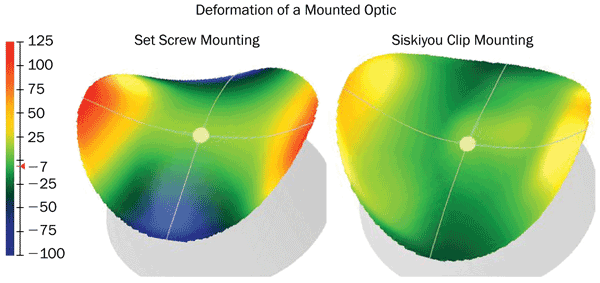
Figure 4. A λ/30 (at 633 nm) optic mounted using a traditional radial set screw, compared with the Siskiyou optical clip. The set screw produces about three times as much distortion as the clip.
Meet the author
John Wingerd is a senior mechanical engineer at Siskiyou Corporation in Grants Pass, Ore.; email: [email protected].