High-speed mosaic strip imaging accelerates 2D and 3D confocal imaging for large fields of neurons and cells.
BARBARA FOSTER, THE MICROSCOPY & IMAGING PLACE INC.
The need to image microstructures over very large areas is driving the next generation of instrumentation in microscopy. The challenge is complex: How can very large areas be scanned quickly and with high fidelity? Conventional wide-field fluorescence microscopes address the issue by adding large, motorized stages to handle multiple slides and/or larger slide formats, but they are slow and often plagued by haze and glare, and are limited in resolution. Confocal microscopy reduces the haze and glare, increases resolution and improves optical sectioning for 3D imaging. The drawback is it can only scan very small areas. Slide scanners, traditionally designed only for bright-field microscopy, are now moving into fluorescence. However, the technique cannot image confocally, losing both fidelity and the ability to optically section. Both confocal — even simple microscope add-ons — and slide scanners also suffer from large footprints, gobbling up valuable bench space.
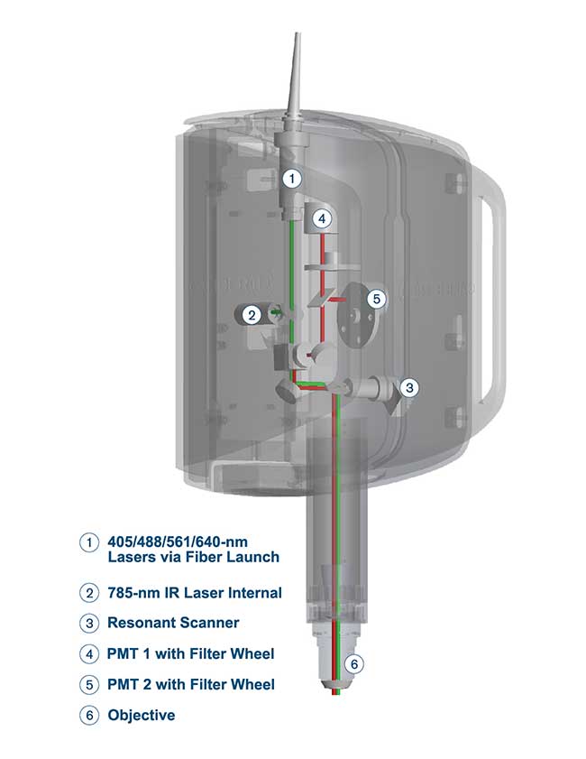
Figure 1. At 200 mm, the RS-G4 light path is short
and simple, maximizing signal-to-noise and contributing to faster
imaging. Courtesy of Caliber I.D.
A new type of instrumentation takes a different approach by combining confocal imaging with high-speed strip mosaic technology to provide speed, high fidelity and large area scanning, all in a footprint about the size of a laptop computer. More specifically, it opens next-generation solutions for research and industry: scanning very large areas, at multiple wavelengths, fast, confocally, with an eye to 3D imaging, all while managing big data smoothly and, literally, seamlessly.
“Where’s the microscope?”
Caliber I.D. took an unconventional approach and designed a flexible, versatile large-format confocal imaging station in an easy-to-use, compact configuration. The first step was the light path (Figure 1). Conventional laser-driven, multiwavelength confocal microscopes put the lasers and/or detectors outside, then wed a scanning system to conventional microscope architecture. The resulting complex of mirrors, prisms, lenses and fiber optics can generate an optical path from the laser to the detector on the order of several meters. Since intensity drops off by the square of the distance, these systems suffer from significant signal loss from both their long path lengths and the interactions at each of the numerous optical interfaces.
Eliminating the microscope stand and using only a few optical elements shrinks the light path to approximately 200 mm. The decrease in optical elements and path length improves efficiency and boosts the signal-to-noise ratio, resulting in shortened dwell time per pixel and high-resolution multiwavelength confocal images in a fraction of the time. Compared to conventional confocals, imaging time drops by 75 to 90 percent, dramatically improving productivity (Figure 2).
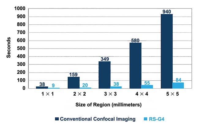
Figure 2. A comparison of imaging speeds between the RS-G4 and conventional confocal microscopy. Courtesy of Caliber I.D.
A different approach to image production
The second major innovation was image construction. Typically, large-format images are formed by collecting images field by field, stopping just prior to image collection to minimize hysteresis and other stage artifacts for each field. The fields are then stitched together to form a large patchwork quilt. Most modern systems also do background correction along the way, to minimize shading errors at the edges of each field. However, these approaches slow down both image acquisition and processing and can still result in residual field boundaries.
In comparison, the new technology coordinates a resonant scanner in the head with continuous stage movement — in essence, unfurling imaging strips rather than collecting individual patchwork fields. As soon as the first two strips are complete, the software goes to work using a proprietary algorithm to align and assemble them with pixel-to-pixel accuracy, resulting in very large-area, seamless image formation at very high speed (see “How High-Speed Strip Mosaic Imaging Works” sidebar).
Large area, fine detail
In microscopy, the ultimate proof is in the image. Figure 3 presents both a large-scale scanned image using the new technique and, in the inset, the deep zoom detail from one small section. The full image is a high-speed strip mosaic created from the scan of 1050 fields of view, covering an area of 12 × 8 mm. This large- area scan was collected and processed in just 270 seconds (4.5 minutes), about one-tenth the time required by other currently available systems.
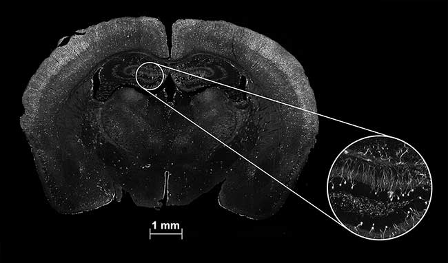
Figure 3. A whole brain section and deep zoom inset of a mouse brain with neurons activated during a stress test. The full-field high-speed strip mosaic image, taken with a 40×/1.30 NA oil immersion objective, covers a scan area of 12 × 8 mm. Made up of 1050 fields, it took only 270 seconds to scan and process. Courtesy of D. Ehlinger and K. Commons, Boston Childrens Hospital.
The inset illustrates the quality of the fine detail. Its high fidelity is generated by the combined benefits of the objective’s high numerical aperture, the confocality of the system and the quality of the image processing. While composed of multiple individual fields, close examination reveals no seams, no edge shading and no field-to-field change in background.
Making life easy for the multi-user lab
Whether advanced instrumentation is used by a single research group or a multi-user core facility, end users require both flexibility and ease of use. The new technology meets those criteria in a compact stand with a small footprint. It also offers multiple viewing angles from 0 to 180 degrees, scan areas up to 120 × 80 mm, and accommodates sample formats from a single microscope slide to very large substrates.
For over 20 years, there has been a debate in microscopy about getting rid of eyepieces. Caliber’s system has none (Figure 4a). The advent of faster computing allows it to mimic the workflow of conventional microscopy. Users can digitally scan a large area at low magnification, acquire a quick “map” to get their bearings, navigate and zoom to an area of interest, then set up and/or apply the experimental protocol. Removing eyepieces from the light path shortens the optical path, reduces light loss at optical interfaces and, in an unexpected benefit, eliminates a potential source of contrast-reducing light leaks.
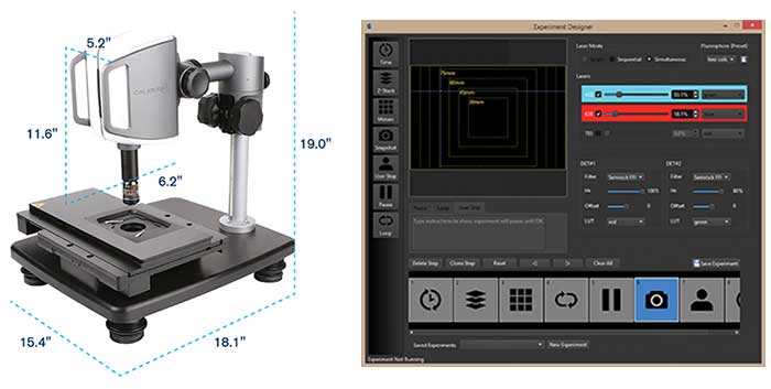
Figure 4. RS-G4 has a small footprint with simple, modular architecture (a) and a flexible, push-button user interface for full control of lasers, scan head and stage (b). Courtesy of Caliber I.D.
Similarly, the new system has streamlined to only one objective, using digital zoom to change magnification on the fly. Different experiments may require different optics, however, so the system supports a wide range of standard dry, oil and water immersion objectives. A “quick change” magnetic mount allows objective exchange in less than 10 seconds.
To accommodate a wide range of imaging requirements, the new technology provides single-channel, simultaneous or sequential reflectance and fluorescence imaging. A multiple laser launch provides excitations at 405 nm, 488 nm,
561 nm, 640 nm and, critical for deep tissue neuroscience, 785 nm.
Users have full control over all laser and scope controls, allowing customization for even lengthy experiments (Figure 4b). Once the parameters are defined, the experiment can be repeated at the push of a button on the screen. The system can scan one large area or the user can mark multiple regions of interest. Once marked, the system will automatically find and scan each area. Different segments can even be imaged using different processes. The simplicity and ease of use result in short learning curves, quick experimental setup and increased productivity in the lab.
When time matters
The determination of washing efficiency is a long-standing industrial challenge, but when the protocol involves live/dead testing for bacteria, time becomes a critical factor. For example, Ewing, N.J.-based Church & Dwight Co. Inc. routinely analyzes the impact of its detergents on bacteria on cloth. Previously, the company was confined to looking at a single small field of view, imaging, then moving to another field. The bacterial population in these samples is sparse, making collection of Live to Dead statistics a challenge (Figure 5). The new technology provides a mark-and-find program that assisted in locating fields with sufficient bacteria to rapidly test various experimental parameters. The system is set to automatically scan user-defined regions of interest over a very large area, equivalent, in the earlier manual experiments, to thousands of fields of view. Afterward, the collected images are fed into third party software for statistical analysis.
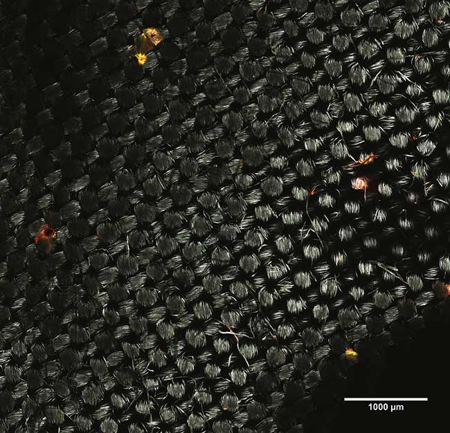
Figure 5. Testing washing efficiency requires scanning a very large area to find sufficient bacteria for Live/Dead ratios. This image was scanned using a 40×/0.75 NA objective using 488- and 561-nm lasers. Live bacteria appear green (GFP); dead, red (RFP). Using the new technology, it took only 90 seconds to scan a 4 × 4-mm area. Courtesy of Mitchell Berman/Church & Dwight Co. Inc.
3D-ready
One important direction of research in The Brain Initiative is to identify cellular interaction within the brain. That assessment requires seeing the brain in 3D. An advantage of confocal imaging is the ability to optically section, allowing the researcher to use thicker sections and to observe neuronal relationships undisturbed.
Figure 6 depicts multiple Z section images taken of the marmoset brain shown in the sidebar. The GFP-stained virus is shown in green (imaged with 488-nm laser) while the Cy5-stained neuronal somata are shown in red (640-nm excitation). This brain section is 20 × 20 mm. Using a 25×/1.10 NA water immersion objective, the system scanned this area in 2500 individual fields. Because this was a dual channel scan, there were actually 2 × 2500 or 5000 fields per plane. Both channels were acquired simultaneously. Scanning and processing time per plane was only nine minutes.
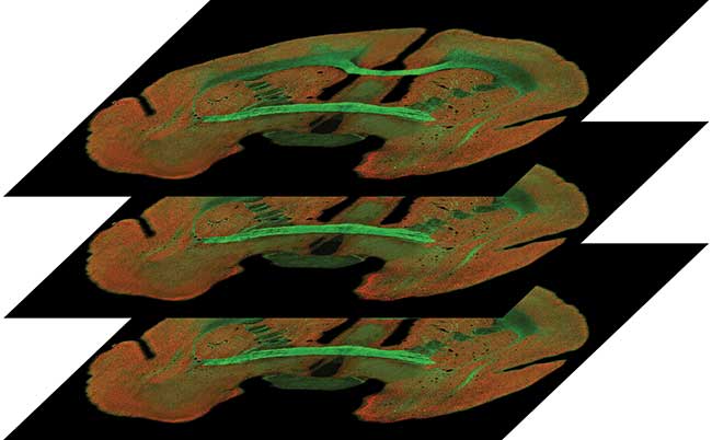
Figure 6. A series of three images from a Z stack, collected from the coronal sections of marmoset brain. Courtesy of A. Rose, P. Strick and S. Watkins, The Center for Biologic Imaging, University of Pittsburgh.
Because the resulting mosaics are stored in universally accepted tagged imaged file format (TIFF) files, they can
readily be exported to third party software such as Image J, Imaris or Media Cybernetics Premium 3D for 3D rendering.
Era of Big Data
Whether in the research lab or in industrial QA/QC, high-fidelity, large-area imaging immediately takes the user into “Big Data” country. For example, in more recent studies related to the marmoset brain discussed above, 2 to 3 GB of data are collected every minute, 24 hours a day, seven days a week.
In the new system, these high data rates are accomplished by running a mid-level computer for image acquisition in parallel with a second computer for image analysis. In addition, it uses a proprietary triple-level file structure. While the explanation sounds complex, this approach is a key element in boosting image processing speed. First, a raw TIFF “snapshot” is captured for every field of view. These are compiled into “Pyramid files” that form an initial image and permit deep zoom. The final mosaic is saved as a high-resolution TIFF image in a “composite” file. These files can be 1 to 2 GB in size and can be single channel or dual channel (two-color) images. For 3D imaging, each image plane will be stored as its own composite file. The user can choose to save files at each level.
Meet the author
Barbara Foster is president & chief strategic consultant at The Microscopy & Imaging Place Inc.; email: [email protected]
How High-Speed Strip Mosaic Imaging Works
Images are built strip by strip, formed by synchronizing the motion of a confocal resonant scanner in the imaging head to that of a high-precision motorized stage. In these examples of a marmoset brain, each image is composed of multiple strips. As soon as the original two strips are completed, a proprietary algorithm working on an integrated, multicore processor begins to align and assemble them with pixel-level resolution. The resulting strip mosaic forms on the fly, eliminating the need for extra processing time.
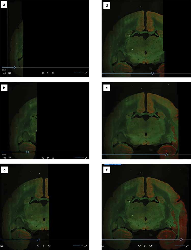
Time slices illustrating building of high-speed strip mosaic of a marmoset brain (a-e), taken using a 25×/1.10 NA water immersion objective. Fluorophores: Cy5 and GFP. The full image covers a scan area of 20 × 20 mm and took a total scan and processing time of nine minutes (f). Courtesy of A. Rose, P. Strick and S. Watkins, The Center for Biologic Imaging, University of Pittsburgh.