The future of scanning vision systems is to make the underlying technology more accessible, robust and foolproof.
From semiconductor manufacturing to the display industry, scanning vision technology is widely found along production lines. In fact, any item that must be made to rigid standards relies on scanning equipment to maintain strict production criteria.
As well as the staple manufacturing industries such as electronics (for printing inspection) and automotive, there is a growing market for vision scanning technologies in the food and beverage, pharmaceutical and medical device industries. These big businesses are relying on optical technologies more and more to satisfy increasingly stringent regulatory requirements.
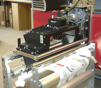
This 100 percent print inspection system features color line-scan cameras. Photo courtesy of Teledyne Dalsa.
As quality control regulations get stricter and companies look for ways to limit defect rates and minimize waste, scanning vision cameras will continue to be a key tool for manufacturers, according to Advancing Vision + Imaging (AIA), the world’s largest machine vision trade group, headquartered in Ann Arbor, Mich.
“Scanning vision systems will likely continue to play a big role in the inspection of both discrete and continuous manufacturing processes,” said Alex Shikany, AIA director of market analysis. “Like other technologies, we see downward pressure on the prices of these cameras with a simultaneous demand for more functionality. Additionally, camera sensors are becoming more advanced as the technology evolves.”
Pressure is mounting to bring the cost of cameras down still further, too, so machine vision companies face an additional challenge: selling their value proposition to small- and medium-sized companies that do not currently employ machine vision technologies.
“As an industry, we need to continue to grow the awareness of what machine vision can do for end users,” Shikany said. “While it takes some investment at the outset, the benefits are plentiful when you look down the road at lower defect rates, higher productivity and efficiency.”
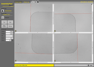
Four-camera alignment: Note that the cameras do not need to be physically aligned. Applications such as module assembly, lamination and cover glass screen printing require 5-µm or better alignment accuracy, and alignment must be done in one step to meet the required line speeds. Photo courtesy of Cognex.
Camera technology advances
With the staggering demand for high-value consumer electronics such as smart-phones, tablets, PCs, high-definition displays and so on, the aim for manufacturers is to move from manual or semiautomated production to fully automated production.
These increasingly everyday gadgets are extremely complex and come with incredibly high quality expectations.
“Lamination, cover glass screen printing and module assembly require 5-µm or better alignment accuracy, and they need it done in a single step to meet the required line speed,” said John Petry, director of marketing for vision software at Cognex Corp. in Natick, Mass., which provides vision systems, software, sensors and surface inspection systems used in manufacturing automation. “Today, these operations frequently require a slow step-and-repeat process because of the limitations of image size and motion control calibration, and the solutions are often ‘brittle,’ requiring frequent machine-specific tuning.”
Although camera resolutions have increased dramatically in recent years (10- to 20-megapixel cameras are not uncommon), they are often impractical, Petry noted.
A four-camera system undergoes calibration with motion stage.
“They frequently can’t image the whole part with enough resolution, especially since the perimeter of the part – which contains the most useful information –
lies near the edges of the image, where lens distortion is worst,” he said. “Imaging the whole part may also require a
large standoff distance, which isn’t always possible. And, of course, a 20+-megapixel camera is still quite expensive.”
The alternative is to use several low-resolution cameras mounted along the sides or corners of the part. This can give highly precise feature measurements from each individual camera, but there is still the question of tying these results into a single overall part location and how to relate this position to the coordinate system of a motion stage that will move the part to the desired target position.
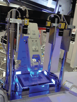
A Mitsubishi light assembly robot and Cognex cameras enable cover-glass pick-and-place. Photo courtesy of Cognex.
One tactic is to design complex mechanical solutions, ensuring that the cameras are all mounted in precise alignment to each other and to the stage axes.
The problem with this approach is that it is expensive and hard to maintain in the field, requiring frequent maintenance by trained technicians: The alignment procedure requires iteration – align, move the stage, then realign and so on – until the part is close enough to the target position.
The newest technology to address this is known as 2-D hand-eye calibration. In this case, the “eyes” are the individual cameras, and the “hand” is a 2-D motion stage on which a part is placed. The technology is derived from multicamera robot-guidance systems, but unlike robot guidance, each camera has a completely independent field of view.
“2-D hand-eye calibration is done by placing a custom checkerboard calibration plate below all the cameras, so that each camera sees a portion of the pattern,” Petry said. “The first step is to perform optical calibration on each individual camera to remove lens distortion and correct for perspective. This is perfectly standard. What is interesting are the next steps.
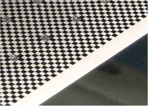
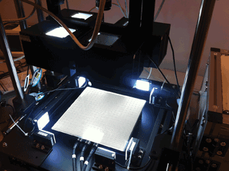
A multicamera calibration plate such as this enables 2-D
hand-eye calibration. Each camera in the system captures part of the
pattern, which is designed so that the camera can “understand” the part
it sees.
“The calibration pattern is designed in such a way that each camera can understand which portion of the plate it sees. This allows the software to determine their spatial relationship and create a unified coordinate space.”
This innovative approach also calibrates the motion stage to the same coordinate space. Thus, with one calibration procedure, users create a single coordinate system that ties all the cameras and the motion stage together. As a result, vision applications can treat the separate camera images as if they were part of a single overall image, even if the cameras are not mounted precisely. They can even have different working distances, optics and orientations.
“Where today many applications require an iterative approach to align parts, systems using 2-D hand-eye calibration frequently achieve 5-µm or better accu-racy during part alignment, eliminating iterative ‘step-and-repeat’ approaches,” Petry said. “And because the calibration procedure can be automated, part changeovers are faster, with minimal downtime and lower support costs.”
Line-scan, area-scan cameras
Line-scan cameras are typically used when there is an uninterrupted high-speed image to capture – paper, glass, metal, etc. – or when high-resolution images are required in a particular area, or the object being scanned is cylindrical in shape.
On the other hand, area-scan systems are more general-purpose than their line-scan counterparts. They typically involve easier alignment and installation, and are often used when the object to be scanned is stationary.
Advancements in speed, resolution and processing power are expected to make these types of cameras more versatile in the future. At the next level, one camera may be able to handle both types of scanning technologies, yet require only simple installation.
One of the newest technologies currently being developed (expected to take around three to five years) is the CMOS time-delay and integration (TDI) imager.
“CMOS TDI will take line scan to the next level with higher speed, better responsivity, lower noise, less power consumption and smaller form factor,” said Xing-Fei He, senior product manager at Teledyne Dalsa of Waterloo, Ontario, Canada, which offers digital imaging and semiconductors. “This is needed for many applications, in particular for color and/or multispectral imaging. In color imaging, [the] spectrum is separated into narrow bands, and therefore sensitivity becomes a crucial issue in high-speed color imaging. TDI is the enabler to overcome the challenge in light-starved conditions.”
The future continues to be very bright for scanning vision systems, as both businesses and consumers demand and expect consistently high quality in the products they purchase, said Pierantonio Boriero, product line manager at Matrox Imaging in Dorval, Quebec, Canada. Matrox develops component-level solutions for machine vision, image analysis, medical imaging and video surveillance.
“Higher camera sensor resolutions and speeds, faster interfaces like 10-GB Ethernet, USB 3.0, CoaXPress and Camera Link HS, and the relentless increases in computing power continue to advance the performance of traditional 2-D scanning vision systems in terms of measurement accuracy and throughput,” Boriero said. “3-D scanning systems, which use basic sheet-of-light or more elaborate pattern-projection techniques, are also becoming more commonplace and are driven by the need to inspect and measure more thoroughly.”