Jason Wickersham, Olympus Industrial America Inc.
Confocal laser scanning microscopy continues to make inroads into industrial inspection applications as diverse as printed circuit boards and automotive components. A key reason is the technique’s analysis flexibility.
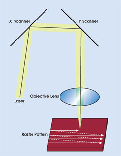
Figure 1. Olympus laser scanning confocal microscopes rely on microelectromechanical systems mirror technology to scan the illumination across the sample.
For example, the latest laser scanning confocal devices, such as Lext technology from Olympus Industrial America Inc. of Orangeburg, N.Y., allow bright-field, dark-field and differential-interference-contrast white light observations in both video and laser confocal imaging modes (Figure 1). Each imaging technique has its strengths:
• Differential-interference-contrast mode allows the examination of subtle textural variations by enhancing the image of a bump or other surface feature by several angstroms. One potential application is detection of scratches on steel plates in an automotive painting process.
• Bright-field imaging, with the specimen observed under white light, is suitable for observing a color filter, ink or metallic corrosion, and for determining the point to be observed.
• Dark-field observation, with the specimen illuminated obliquely, allows viewing of only the light being scattered from the edges where there are minute bumps or level differences. In semiconductor manufacturing, this technique can detect flaws and crystal defects on a bare wafer.
Researchers also can simultaneously image samples in three dimensions and true color by combining the acquired laser three-dimensional image with the full-color bright-field image in the system computer. Imaging resolution is 0.12 μm and, depending on the application requirements, microscope magnification power can range from 120× to 14,400×. To better understand this latest generation of technology, it helps to examine how the instruments differ from conventional reflected-light microscopes.
With conventional microscopes, the light coming from the condensing lens uniformly illuminates the sample surface. As a result, rays of light reflecting and scattering from various points on a specimen often overlap. With a reflected-light microscope, for example, light reflects from each point on the sample toward the detector (Figure 2, left). The red lines in the illustration depict light coming from the focal plane, and the blue lines represent light from planes outside the focal plane. The resulting image is a product of both in- and out-of-focus light, which can degrade its contrast and resolution.
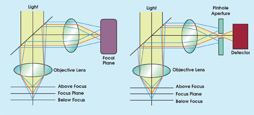
Figure 2. Because of the nature of the optical system with conventional reflected-light microscopes, out-of-focus light can cause deterioration of image quality (left). Pinhole apertures used in a confocal optical system can prevent that light from reaching the detector (right).
The Olympus confocal optical system uses a circular (pinhole) aperture in the conjugate focal plane of the specimen to keep out-of-focus light from reaching the detector (Figure 2, right). Move the sample from a position below focus to one above focus, and the reflected light intensity will start low, reach a peak and fall off again. Without the pinhole aperture, the width of the generated waveform is relatively broad (Figure 3). With the aperture in place, the peak narrows and the system performs in a way that is very close to the theoretical predictions. This boosts resolution along the optical axis and allows precise Z-axis measurements.
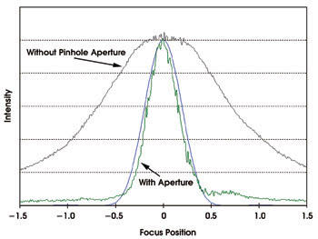
Figure 3. The graph of the intensity profile vs. focus position illustrates the close correlation between theoretical and actual results with laser scanning confocal microscopes.
To build a useful image, the illumination point must be swept across the sample surface. Either the stage must move precisely back and forth in X while also traveling in Y, or scanning mirrors can be used to direct the illumination across the surface of a stationary sample.
One advantage of this second strategy is that there are fast image acquisition speeds. It also is possible to use an optical zoom to magnify images. This is done by changing the scan angles of the mirrors in such a way as to sweep a smaller portion of the sample. The image, however, is still viewed in the same size window, unlike when a digital zoom is used. In that case, an area of interest in an image is simply enlarged, often making the image fuzzy.
With the latest generation of confocal devices, the calculated focus operation is key to the system’s ability to achieve clear focus in three dimensions. Z-position is determined by computing the results of scanning, not by moving the objective lens and locating the brightest point, as with other types of microscopes. Although conventional confocal laser scanning microscopes acquire 3-D images by stacking multiple image planes taken from the scanning of a component throughout its height at regular submicron steps, the Lext microscope uses an intelligent software drive to select the optimum focal planes to form the image.
This feature speeds the operation and helps ensure the best focal fit for each of the selected planes. Because the microscope control captures height and brightness data simultaneously, image acquisition is very quick, with 100 to 125 image slices captured in about 60 seconds.
Conclusions
Ultimately, the illumination wavelength and the numerical aperture of the objective lens dictate possible resolution. To improve resolution, one must lower the wavelength of light used for illumination or increase the objective lens’s numerical aperture. Using conventional microscopes with white light, estimates of resolution are frequently based on 550 nm, the green region of the spectrum that the human eye is most sensitive to. Thus, with a high-resolution objective lens (100× and 0.95 NA), conventional microscopes are limited in resolution to about 0.35 μm. Chromatic aberration also could limit resolution, depending on the amount of correction in the objective.
The Olympus laser scanning confocal microscope uses a 408-nm laser diode as the illumination source. Because lasers are highly monochromatic, chromatic aberration is reduced. The instrument also contains a detector that operates at this wavelength and a custom-designed optical system. Because of these improvements and the confocal aperture, typical resolution of the system for the same objective is in the range of 0.12 μm.
Meet the author
Jason Wickersham is a product manager with Olympus Industrial America Inc. in Orangeburg, N.Y.; e-mail: [email protected].