A single FBG can provide tunable dispersion compensation for all channels of a modern wavelength division multiplexing system.
Dr. Martin Guy and Dr. Yves Painchaud, TeraXion Inc.
Chromatic dispersion compensation is recognized as one of the main challenges in high-data-rate optical communications systems. Dispersion directly affects the quality of the data transmission and causes a blurring of the bit stream. Dispersion-compensating fibers are widely used to compensate for this effect.
Fiber Bragg gratings (FBGs) also have been proposed for this function and are recognized as an alternative to dispersion-compensating fibers, with advantages regarding insertion loss, footprint, nonlinear effects and cost. Although initially limited to single-channel operation at a fixed dispersion level, significant advances have been realized over the past few years. FBG-based solutions that allow static and tunable dispersion compensation over the full C- and/or L-band are commercially available.
Chromatic dispersion
Chromatic dispersion in an optical fiber is a phenomenon caused by the wavelength dependence of its group index. (Fiber Optics 101: The group index of a fiber depends on both the bulk refractive index of the material and the propagation properties of the waveguide.)
The light propagating through the optical fiber carries information in the form of a pulse stream. Each light pulse has a frequency content that depends on its temporal shape. The shorter the temporal width of the pulse, the wider its frequency spectrum. The wavelength dependence of the optical fiber group index causes a temporal broadening of the pulses as they propagate. Chromatic dispersion is thus a temporal spreading over the wavelength spectrum and is expressed in units of picoseconds per nanometer for a given fiber length.
After a certain propagation distance, the broadening of the pulses causes a significant number of errors at the receiver end. As data rates in optical networks increase, the negative impact of dispersion increases dramatically.
For example, the deleterious effect of dispersion is 16 times greater in a 40-Gb/s system than in an OC-192 10-Gb/s system. That’s because the spectral width — and, hence, the pulse stretching — increases by a factor of four, while the tolerance for stretching (i.e., the spacing between the pulses) decreases by a factor of four.
Fortunately, even when the pulses are so severely broadened that the pulse stream cannot be recognized, the information is not lost. It is rather like the image that enters the eyes of a myopic person: Although the image is blurred such that the person cannot read the letters on a panel, an appropriate correction, such as glasses, fully clarifies the image. In the same manner, a dispersion compensation device is used to recover the information by removing the pulse-broadening effect.
Dispersion compensation
Chirped FBGs are suitable candidates for compensating the chromatic dispersion that occurs along a transport optical fiber link.1 An FBG is a reflective device composed of an optical fiber that contains a modulation of its core refractive index over a certain length. The grating reflects light propagating through the fiber when its wavelength corresponds to the modulation periodicity.
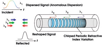
Figure 1. A chirped fiber Bragg grating compensates for dispersion by reflecting different wavelengths at different locations along the grating axis.
In a chirped FBG, the periodicity of the induced index modulation varies along the grating’s length (Figure 1). As the grating period varies along the axis, the different wavelengths are reflected by different portions of the grating and accordingly are delayed by different amounts of time. The net effect is a compression (or a broadening) of the input pulse that can be tailored to compensate for the chromatic dispersion accumulated along the fiber link. Although entering the grating at different times, the wavelength components of broadened pulses all return to the entrance at the same time.
The optical characteristics of such a device are mainly the reflectivity spectrum, which shows the wavelength range of operation, and the group delay spectrum, which provides the dispersion characteristic (Figure 2). The slope of the group delay spectrum is the dispersion of the device. FBGs are fabricated by focusing a UV beam into the core of an optical fiber, producing a permanent index change. The grating is conveniently obtained by using a phase mask.2 The phase mask, located in proximity to the fiber, produces an interference pattern that creates the desired spatial modulation of the index change.
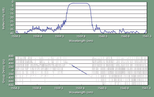
Figure 2. Typical reflectivity (top) and group delay (bottom) spectra of a chirped fiber Bragg grating were tailored for compensating the chromatic dispersion accumulated along 80 km of SMF-28 fiber.
For broadband operation using FBGs, many solutions have been proposed. Ultralong gratings of a few meters were one of them, but they are difficult to produce in volume and typically suffer from high group delay ripples. Another approach uses amplitude sampling for multichannel dispersion compensation. The complex nature of an amplitude-sampled Bragg grating apodization profile increases as a function of the total bandwidth. This complicates the fabrication of a dispersion compensation grating over a large number of channels. Moreover, the writing of an amplitude-sampled Bragg grating requires a complex apodization profile that includes a large number of phase shifts.
Another approach superposes multiple Bragg gratings on the same section of an optical fiber. High-channel-count chromatic dispersion compensators using superimposed chirped FBGs have recently been obtained and proposed as an alternative to dispersion-compensating fiber for third-order dispersion compensation and for dispersion slope compensation.3
Such a multichannel device works the same as the single-channel device of Figure 1, except that it operates over many wavelength bands instead of only one.
The complex phase mask
Although each grating component of a multichannel FBG fabricated by superposition can be considered as a standard chirped FBG, the overall grating is quite complex and not well-suited for mass production.
The transfer of the FBG complexity from the recording process into the phase mask constitutes an important breakthrough that significantly improves manufacturability (Figure 3).4 When fabricating a simple FBG filter, a standard phase mask is usually used along with a fixed UV laser beam (Figure 3a). This technique is similar to the one used for the fabrication of simple FBG devices such as pump laser stabilizers. This recording technique is very efficient but can be applied only to simple FBG filters. One of the most common techniques for fabricating an FBG filter that requires a complex apodization profile and that uses a standard phase mask involves a complex recording scheme where the UV laser beam is scanned along the phase mask (Figure 3b).
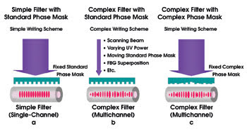
Figure 3. To make a simple FBG filter, a standard phase mask along with a fixed UV laser beam is usually used (a). To fabricate an FBG filter that requires a complex apodization profile using a standard phase mask requires a complex recording scheme where the UV laser beam is scanned along the phase mask (b). A complex phase mask can be used for the fabrication of a complex FBG filter by transferring the complexity of the recording scheme directly into the phase mask (c).
The complexity of this technique makes it far less suited for mass production. The objective is to use a very simple recording scheme such as the one depicted in Figure 3a, while producing a very complex FBG filter in a cost-effective manner. This can be accomplished by transferring the complexity of the recording scheme directly into the phase mask (Figure 3c). A fixed UV laser beam shines on a complex phase mask to produce a complex filter similar to the one obtained with the recording setup in Figure 3b.
One of the most powerful and elegant approaches to producing high-channel-count FBGs is to use a sampling method, a spatial modulation of its physical properties (apodization and/or phase).5 This modulation allows the FBG to reflect over multiple spectral peaks instead of over only one. If the sampling pattern has a constant period P, each peak presents the same optical characteristics, and the peak spacing is given by:
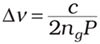
where ng is the fiber group index.
The use of phase-only sampling is particularly attractive because no fiber is wasted as in the amplitude-sampling approach. Accordingly, a larger number of peaks can be obtained with the same refractive-index change.5 The phase-sampling technique is easy to implement directly into a phase mask using advanced lithographic tools that can accurately position the grooves on the mask (Figure 3c).
In the results obtained for a static 51-channel dispersion compensator with 100-GHz channel spacing, the phase sampling pattern was encoded directly into the phase mask (Figure 4). When a simple UV beam illuminates the mask (Figure 3c), it creates a multipeak pattern in the fiber behind the mask. Each of the 51 peaks in this grating can compensate for the chromatic dispersion of one of the 51 channels of an 80-km SMF-28 fiber link.
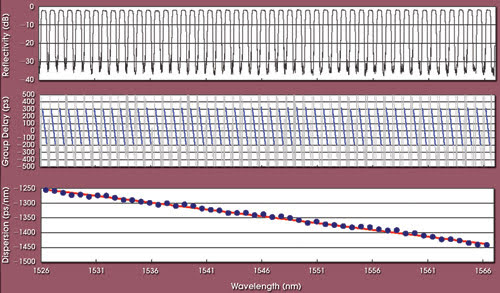
Figure 4. The results obtained for a static 51-channel FBG-based dispersion compensator show the reflectivity (top) and the group delay (center) spectra. The dispersion values obtained from linear fits of the group delay spectrum are also shown (bottom).
Using the phase-sampling approach, excellent optical properties are obtained, as can be seen in Figure 5, which shows a zoom over the first three channels. Although using a sampling function with a uniform period along the grating enables the acquisition of identical replicas, a sampling function with a chirped period allows a dispersion level that varies from channel to channel.6
This is a relevant feature because the dispersion of optical fiber is not uniform along the spectrum. Accordingly, a dispersion-compensation device, including the so-called slope-matching, is achievable with this technology.
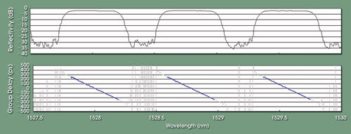
Figure 5. This chart depicts the reflectivity (top) and group delay (bottom) spectra of the first three channels of a static 51-channel FBG-based dispersion compensator.
Dispersion tuning
FBG technology is also well-suited for tunable dispersion compensation. Submitting the FBG to a temperature gradient allows the grating chirp to be changed and, accordingly, the dispersion level to be tuned.7 Single gratings can be used for producing negative dispersion over a typical range from –800 to –2000 ps/nm or for producing a similar positive dispersion range.
Although dispersion compensation typically requires a negative range, a positive range is also of interest for dispersion-emulation applications. A pair of FBGs also can be used for operation around 0 ps/nm with a typical dispersion range of –1000 to 1000 ps/nm. In the group delay spectrum over three channels of a 51-channel FBG for different temperature gradients imposed on the fiber, dispersion tuning corresponds to dispersion levels of –570, –990 and –1490 ps/nm (Figure 6).
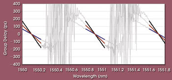
Figure 6. The group delay spectra of three channels of a 51-channel dispersion-compensation FBG resulted from adjusting the dispersion by a thermal gradient.
A cost-effective alternative
Fiber Bragg gratings are a mature technology that is very well adapted for dispersion compensation in optical communications systems. With all of the aforementioned developments, FBG-based technology can be considered a cost-effective alternative to competing technologies while providing major advantages such as small size, no nonlinear effects and low insertion loss.
References
1. F. Ouellette (1987). Dispersion cancellation using linearly chirped Bragg grating filters in optical waveguides. OPT. LETT., Vol. 12 (10), pp. 847-849.
2. K.O. Hill, B. Malo, F. Bilodeau, D.C. Johnson and J. Albert (1993). Bragg gratings fabricated in monomode photosensitive optical fiber by UV exposure through a phase mask. APP. PHYS. LETT., Vol. 62 (10), pp. 1035-1037.
3. Y. Painchaud, A. Mailloux, H. Chotard, E. Pelletier and M. Guy (2002). Multi-channel fiber Bragg gratings for dispersion and slope compensation. Proc. OFC 02, pp. 581-582.
4. M. Guy, F. Trépanier and Y. Painchaud (2003). Manufacturing of high-channel-count dispersion compensators using complex phase masks technology. Proc. BGPP 03, pp. 269-271.
5. J.E. Rothenberg, R.F. Caldwell, H. Li, Y. Li, J. Popelek, Y. Sheng, Y. Wang, R.B. Wilcox and J. Zweiback (2002). High-channel-count fiber Bragg gratings fabricated by phase-only sampling. Proc. OFC 02, pp. 575-577.
6. M. Morin, M. Poulin, A. Mailloux, F. Trépanier and Y. Painchaud (2004). Full C-band slope-matched dispersion compensation based on a phase sampled Bragg grating. Proc. OFC 04, paper WK1.
7. R. Lachance, S. Lelievre and Y. Painchaud (2003). 50 and 100 GHz multi-channel tunable chromatic dispersion slope compensator. Proc. OFC 03, pp. 164-165.
Meet the authors
Martin Guy is vice president of development at TeraXion Inc. in Sainte-Foy, Quebec, Canada; e-mail: [email protected].
Yves Painchaud is development manager at TeraXion.