As developing technologies and regulations affect automobile design, 3D optical profiling offers manufacturers new ways to improve processes and reduce costs.
SAMUEL LESKO, BRUKER NANO SURFACES
The automotive industry has undergone major changes over the past couple of decades because of a combination of internal and external factors that include competitive cost-reduction actions and increased environmental regulations. These factors have fostered widespread innovation in the mass-production automotive industry, and the continuous development of new technologies has, in turn, enabled a clearer understanding of the fine details of how an automobile operates.

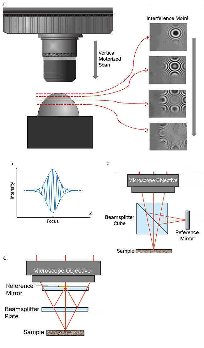
Figure 1. Principle of white-light interferometry (WLI) applied to noncontact profiling. Vertical scan acquires moiré at different heights of spherical-shaped sample (a). The coherence envelope plots intensity and focus to create an optical path difference (OPD) file (b). Michelson objective configuration (c). Mirau objective configuration (d). Courtesy of Bruker Nano Surfaces.
While the automotive industry has thoroughly implemented long-established industrial metrology techniques such as stylus profiling, recent innovations require the use of equally advanced metrology — such as noncontact optical profiling — together with newly introduced areal texture parameters from ISO norm 25178. The latest generation of white-light interferometry (WLI) technology also supports today’s automotive improvements, and its role as a superior optical profiling method will be discussed in three case studies.
Optical profiler technology
Noncontact profilers cover a spectrum of techniques and methods and rely on different technologies to capture surface topography via a derived optical signal. Generally, these varied approaches incorporate an optical stand equipped with objectives, a digital camera, and scanner motor to efficiently capture full areas. The scanner ensures the vertical displacement of the objective all the way through the focus, while the camera simultaneously records a series of intensity frames, from which the height position for each pixel is worked out to rebuild topography.

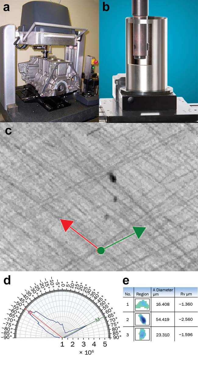
Figure 2. A full engine under investigation for bore cylinder roughness (a). Illustration of depth penetration (b). Typical results of crosshatch topography (c) with polar analysis of power spectrum density (d) and automatic pit characterization (e). Courtesy of Bruker Nano Surfaces.
This intersects with techniques such as confocal imaging (excluding laser-scanning confocal imaging), WLI (also referred to as coherence-scanning interferometry, or CSI), and focus variation. These techniques, although similar, differ in how intensity is processed to determine the position of best focus and subsequent height position. When compared to 2D techniques employed by stylus-based and optical-pen-based profilers (chromatic confocal imaging or autofocus), WLI offers the major advantage of short measurement time combined with full capture of the area.
Among 3D optical profilers, WLI will exhibit specific technical advantages because of the use of an interferometric objective and the presence of an interference pattern within the focal plane. The use of a low-coherence source, usually LED, means the interference pattern only shows up within ±0.5 µm around best focus, which acts as a well-defined, unambiguous marker of best focus. Furthermore, the sharp rise and fall of intensity around the coherence length allows the algorithm to refine vertical position within a few nanometers, and in some instances even in the Angstrom level, leading to unmatched vertical resolution across the whole range of optical profilers.
Another benefit of using a WLI interference pattern is that the vertical resolution becomes fully independent of the chosen objective, while lateral resolution remains linked to numerical aperture. Among 3D optical profilers, this is a unique characteristic that allows, for instance, the use of low magnification to cover larger areas and gain throughput, as well as the use of extra-long working distance objectives to get access to hidden areas. All mentioned configurations are possible without compromising vertical resolution (Figure 1).
The following case studies emphasize how beneficial these characteristics are to specific automotive metrology applications.
Bore cylinder measurement
The evolution of environmental norms and the need to improve a car’s fuel efficiency have been strong drivers for motor and overall powertrain redesign. Notably, the engine itself has undergone major changes to dramatically reduce weight and boost performance. One critical change takes place in the bore cylinder, where the piston slides up and down inside the chamber at each combustion cycle and transfers motion to the wheels through camshafts. While the entire mechanical chain can be improved, the first-order gain can be achieved by lowering the friction between the piston ring and chamber while still ensuring perfect tightness of the combustion chamber.
One solution, adopted by automotive manufacturers for many decades, has consisted of texturing the surface with a crosshatch pattern (honing), which creates a regular groove structure with two well-defined directions. The grooves act as a lubricant reservoir at each cycle, facilitating the sliding motion of the piston inside the cylinder. Homogeneity of groove depth and orientation/angle between texture directions, as well as the presence of material protrusion above the bearing plane, all greatly impact not only performance gains but also engine lifetime.
For this solution, it is critical to ensure proper production via thorough quality control of the surface roughness of the bore cylinder. Challenges arise, however, because of geometric restriction, as the measurement must take place inside a cylinder or even directly inside an assembled engine. Furthermore, honing structures to reach submicron-roughness level requires nanometer precision.
For the largest engines used for trucking or even marine applications, a replica coating technique that can be peeled off the surface while retaining surface features provides a workable solution. Besides its usual dark color, a replicated surface can be successfully measured
ex situ by using the WLI technique with a regular 5× or 10× Michelson or Mirau interferometric objective.
For direct in situ measurement, the WLI technique allows the use of super-long working distance objectives based on a Linnik configuration. This ensures both illumination homogeneity and minimal aberrations on the optical beam along 2×, 5×, and 10× magnifications, while preserving nanometer vertical resolution. Adding a mirror in the sample-optical path results in the unique capability to directly measure sidewall roughness from a bore cylinder. Variation in mirror size allows access to bore cylinder diameters as small as 10 mm and to a penetration depth as much as 46 mm.

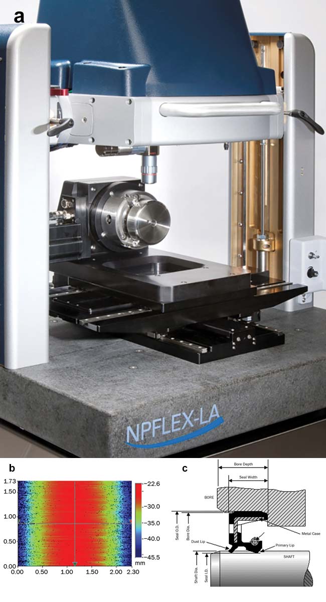
Figure 3. Lead analysis on a standard sample (a, b). Schematic of rotary dynamic seal (c). Courtesy of Bruker Nano Surfaces.
As the piston ring travels the stroke length inside the cylinder, there is a need to control surface texture at different penetration depths. An optical solution has been designed through the Michelson configuration to extend standard 5× interferometric objectives to achieve up to
150 mm penetration length. Typical measurements exhibit a mean areal roughness (Sa) between 0.2 and 0.05 µm, depending on the penetration depth inside the bore or on the honing process. Crosshatch structure is nicely captured and automatically analyzed through an angular power spectrum to derive the angle between both directions. The bearing curve and associated roughness parameters from functional parameters (stratified surface and volume) allow direct correlation with lubricant retention and wear resistance, which are key criteria for performance. Finally, WLI measurements of diameter, maximum depth, and volume can automatically detect and rank defects (Figure 2).
Shaft lead-angle measurement
WLI can also provide a superior
metrology solution further down the power train. For example, rotary dynamic seals on Cardan shafts or camshafts help transfer power to the wheels. These rotating connections are seated around a shaft that is lubricated to improve fuel efficiency, and the sealing gaskets aim to retain oil and prevent leakage. For optimal operation, extended lifetime, and ultimate reliability of vehicles, the design of the shaft becomes critical.
On the one hand, the surface roughness of a shaft needs to fit within a specific narrow window. If the shaft is too rough, not only will the seal — which is in tight contact with the rotating shaft — abrade quickly, but it will also create a direct path for oil to leak through the valleys of the surface texture. On the other hand, if the shaft roughness is insufficient, two problematic phenomena will occur: The large contact area between the seal gasket and shaft will potentially create a sticking issue at engine start, and the overly smooth surface of the shaft will also eliminate oil reservoirs that help lubricate the contact area. Both problems lead to premature aging of a seal and unexpected failure and/or leakage. The ISO standard 6194-1:2009 for rotary-shaft lip-type seals recommends mean roughness between 0.2 and 0.5 µm.
In addition to surface roughness, the orientation of surface texture also affects a seal’s effectiveness. Since the shaft is a cylinder in rotation, any groove left away from the shaft axis acts as an Archimedes’ screw, pumping fluid outside (leakage) or inside (drying). The angle between grooves and shaft is called the “machine lead,” “lead angle,” or simply “lead,” and for best performance measurements it targets a zero value. Current standards specify shaft leads of less than 0.05°.
3D optical profilers based on the WLI technique perfectly address characterization needs with such tight tolerances. Sub-micron roughness is accurately measured with repeatability below 2 nm (one sigma) on shafts, and — in a single shot — they combine fast vertical scanning (5 s) with measurement of millimeter-square areas. Throughput is indeed essential for lead-angle characterization to accurately measure orientation of surface grooves versus cylinder axis.

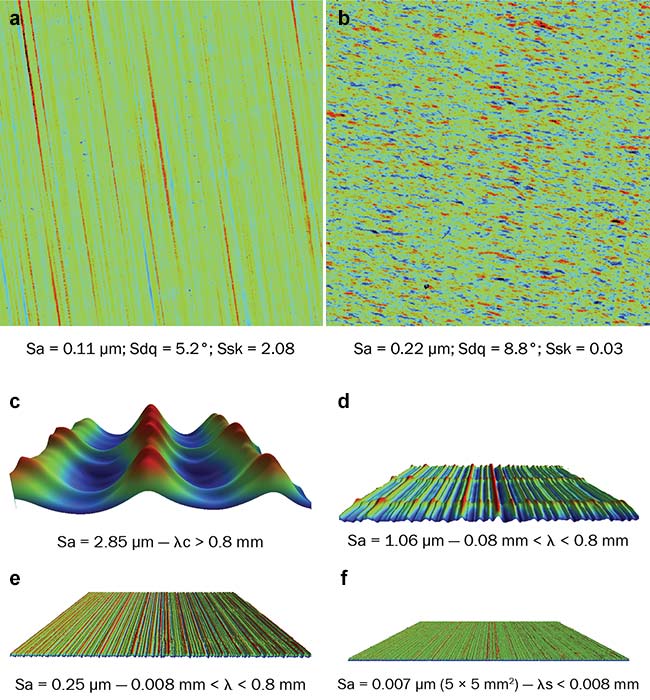
Figure 4. The difference between shiny (a) and matte (b) aluminum rods with associated roughness parameters. Decomposition of textured plastic dashboard versus different spatial wavelengths (c-f). Courtesy of Bruker Nano Surfaces.
The relative angle of the camera sensor versus the shaft should be assessed, as well as the possible mismatch between the mounting clamp and the tested shaft. To leverage out uncertainties and operator dependence, this solution measures the shaft in more than 100 different locations along its length and at regular multitheta positions. On each image, the instrument derives the mean angle of lead grooves through the angular power spectral density, where grooves show as strong peaks at an angle corresponding to their pitch relative to the camera’s image grid.
By fitting a surface-curve model to the texture map, the 3D profiler can determine the degree and orientation of any misalignment between the image grid and the shaft axis, allowing the average angle of those grooves relative to the shaft axis to be calculated, thus providing an accurate measure of lead pitch (Figure 3).
With such an approach, 3D optical profiling achieves highly accurate metrology results on the lead angle, with static repeatability below 0.005° and dynamic repeatability at 0.02°. Since modeling takes into account misalignment of the shaft versus the mount, measurement also becomes user- and platform-independent. Known 0.4° right-hand and left-hand lead shafts were successfully measured in full gauge repeatability and reproducibility (GR&R) tests over three different machines and three different operators. Results showed maximum deviation between 0.04° and 0.08°, confirming the superior accuracy of the lead-angle measurement.
Dashboard appearance measurement
A car’s interior not only plays a key role in buyer perception, it also has a true functional nature. A car dashboard, for instance, is designed so no straight light is reflected back to the driver, helping to avoid distraction or disturbance of view. Meanwhile, the same dashboard may contribute to the overall ambiance of the vehicle interior by simulating leather or wood surfaces and mimicking imperfections, regular granularity, or even shininess. These subjective parameters can be challenging to gauge or monitor in production. As demonstrated in the previous two case studies, these concerns may benefit from quantitative metrology in efforts to develop a new product.
Dashboard development and evaluation can be addressed with various metrology approaches. The first combines real topography measurement with light simulation. A few-cm2 board sample, large enough to capture texture, was fully measured with a noncontact profiler. The results were converted into a 3D-format file (an STL), which was then transferred into modeling software. The software paved the entire car dashboard with the initially recorded sample and then used the bidirectional reflectance distribution function (BRDF) to render the way light reflects. This provided a virtual representation of how the dashboard would look.
Among 3D optical profilers, white-light interferometry will exhibit specific technical advantages because of the use of an interferometric objective and the presence of an interference pattern within the focal plane.
Multiple motifs were then quickly screened and ranked. Since the actual production of a completed dashboard was skipped for each sample candidate, considerable cost savings were realized by the WLI measurements for this development stage. This simulation protocol worked only because the WLI profiler
accurately reproduces surface contours and textures. Such precision relies on a robust algorithm, an optimal lateral
resolution for a given objective, and nanometer-level vertical resolution even at lower magnifications. Objectives of
5× or 10× are usually preferred to reduce stitching time for regions of interest, as well as to reach micrometer-level spatial wavelength, which together are critical to represent the interaction of visible light with matter.
The second approach relies on a deep analysis of surface texture through advanced areal roughness parameters from ISO norm 25178, which provides powerful quantified values that correlate very closely to appearance. The distinction between shiny and matte metallic rod surfaces in car interiors is quantified nicely, for instance, through a mean slope parameter (Sdq) measurement. This parameter translates average slope fluctuation along a measured area in direct correlation to how light reflects in single or multiple directions. In some instances, well-accepted Sa parameters can lead to the same conclusion; however, careful spatial filtering via the robust Gaussian method is necessary to extract the proper spatial frequency responsible for light scattering.
Dashboard topography was successfully analyzed by this second approach
to discriminate between the visual perception of ghosted and non-ghosted surfaces. For this specific application,
the skewness parameter (Ssk), which
represents height distribution, was found to be the most effective differentiator, with an almost 2.5× change between ghosted and non-ghosted areas. The main root cause of this optical phenomenon arises from the fine microroughness that superimposes over large surface waviness. The WLI technique uniquely offers a combination of high lateral resolution and high vertical sensitivity that makes it possible to resolve large vertical depths from motifs, and/or smooth surfaces left by the imprinting/molding process (Figure 4).
To conclude, a noncontact optical profiler based on WLI enables a wide range of precise characterization for automotive manufacturing, from motor efficiency to customer perceptual appreciation of a car’s interior. Direct conclusions can be quickly established in a reliable manner, thanks to the unique nanometer accuracy of optical profiling over larger areas. Capability is further extended by super-long working distance objectives to probe surfaces that are usually a challenge to access.
Meet the author
Samuel Lesko has more than 18 years of optical profiler applications experience, particularly in using white-light interferometry
in a wide variety of industries, from MEMS and semiconductor to automotive and aerospace. Lesko received a doctorate in physics and a materials science engineering degree from the University of Burgundy in France; email: [email protected].