The technology overcomes the diffusion limit and could play a key role in many health care applications, including dental imaging and cancer detection.
PANTEA TAVAKOLIAN, SOHRAB ROOINTAN, KONESH SIVAGURUNATHAN, AND ANDREAS MANDELIS, UNIVERSITY OF TORONTO
Imaging plays an important role in disease prevention, diagnosis, and treatment, and new technologies are helping to overcome many limitations to resolution and depth. Early diagnosis of diseases can alter the path of treatment and its efficiency enormously. For instance, dental caries can be treated noninvasively through remineralization, if detected early, before the need to drill the tooth.
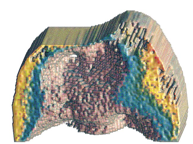
A reconstructed image of the distal surface of a tooth. Courtesy of University of Toronto.
In recent years, optical imaging techniques have steadily established their unique advantages in biomedical imaging methods, thanks to their capacity for high-contrast and high-resolution imaging. However, purely optical methods are hindered by their penetration depth, which is affected by the optical diffusion length limiting their biomedical applications. Biothermophotonics is a novel noninvasive imaging method that overcomes some of the major limitations of purely optical imaging of hard and soft tissues, while retaining its unparalleled molecular specificity.
Photothermophotonic (or, simply, thermophotonic) imaging technologies exploit the optical-to-thermal energy conversion to provide penetration depth beyond the optical diffusion length. These technologies are based on the photothermal effect, which is the nonradiative conversion of the energy of photons irradiating and absorbed by a material into heat, which subsequently propagates conductively and/or radiatively. The latter pathway leads to radiation heat transfer (Planck emission) of thermal infrared (IR) photons. Thermophotonic imaging involves the detection of such IR photons from tissues captured by mid-IR cameras. This approach to biological/biomedical imaging bears many similarities to photoacoustic imaging.
Although the image source generation process in optically absorbing media is the same for both photoacoustics and thermophotonics, both of which feature optical-level contrast, there are added advantages to the latter, including:
- Direct signal transmission through air rather than through an ultrasound couplant fluid interface.
- Full-area imaging CMOS or CCD arrays built into commercially available IR cameras, which avoids mechanical scanning of transducer arrays.
- Relative image processing and interpretation simplicity due to direct conversion of light into heat without the complexities of intermediate thermoelastic processes.
- Equipment portability, including
the camera.
- Simplicity and relatively low price based on small-size wavelength-selective laser diode sources.
Some obvious disadvantages also lie in the energy evolution past the absorption process in thermophotonic imaging, including the shallower subsurface thermal signal transport compared to ultrasound, and several image-quality issues related to the physical fundamental differences between acoustic and thermal fields.
When an incident photon beam that generates photothermal fields is intensity-modulated using single- or multifrequency waveforms, the resulting heating and cooling oscillation cycle is known as a thermal wave. In contrast to electromagnetic and sonic waves that obey hyperbolic differential equations and exhibit wavefronts propagating at finite velocities, thermal waves are governed by the parabolic heat diffusion equation and thus are lossy with no wavefront structure1. This critical difference leads to depth-integrated (i.e., not localized, or, in other words, diffusive) energy distribution. This property of thermal waves results in poor axial and lateral resolution for thermophotonic technologies and makes it challenging to create three-dimensional images using thermal waves.
Overcoming diffusion barrier
To overcome poor axial resolution, a cutting-edge thermophotonic imaging modality called truncated-correlation photothermal coherence tomography
(TC-PCT) has been introduced at the Center for Advanced Diffusion-Wave and Photoacoustic Technologies in Toronto2; and subsequently at Harbin Institute of Technology, Hunan University, and Tsinghua University in China; and the University of L’Aquila in Italy. This modality exhibits a high degree of energy localization in a parabolic diffusion-wave field through time-evolving axial filtering controlled by pulse delay and cross-
correlation (CC) truncation. The axial filter is correlated time-slicing embedded in the image-processing algorithm and produces depth-resolved image slices. This adds crispness to reconstructed TC-PCT images because it eliminates diffusion-limited contributions from above and below a subsurface location. Such contributions tend to totally or partially dominate the thermal-wave signals, especially those from deep regions in conventional depth-integrated photothermal imaging. The result is that hidden/weak absorption features now appear in the respective subsurface image slice.
Stacking up all such image slices produces a three-dimensional image made of consecutive coherent (i.e., coordinate matched through fixed phase delay) planar images reminiscent of optical coherence tomography. A major advantage of TC-PCT is the operator-controlled axial resolution, a function of the truncated cross-correlation time-slice thickness. To address the lateral resolution challenge associated with diffusion-wave fields, a more recent enhanced version of TC-PCT (eTC-PCT)3 exhibits improved signal-to-noise ratio and the ability to produce three-dimensional thermophotonic images with improved signal-to-noise ratio. A unique spatial-gradient-gate adaptive filter is employed in a scanned mode along the (xy) coordinates of camera image slices from various tissue depths, revealing absorber true spatial extent from diffusive photothermal images, and restoring prediffusion lateral image resolution beyond the Rayleigh criterion limit4.
As a result, eTC-PCT has largely overcome the intrinsic disadvantages of diffusive imaging, becoming a promising noninvasive and noncontacting imaging modality platform with the potential for a wide spectrum of applications, and enabling the emergence of three-dimensional biothermophotonic imaging.
System setup for stacking
A typical embodiment of eTC-PCT uses a simple setup, presented in Figure 1a, comprising an 808-nm diode laser (other wavelengths can be used, leading to multispectral eTC-PCT), a mid-IR camera, and a function generator that triggers both the camera and the laser driver. The reconstruction algorithm and synchronization of the systems are operated on a computer. The sample is positioned at the focal plane of the camera and is subjected to chirped pulse laser irradiation (a linear frequency modulation, or LFM, excitation chirp) during which the camera records the sample’s thermophotonic relaxation signal that represents the evolution of temperature at each point on the sample matrix. A reference chirp is generated based on the excitation chirp. And subsequently, for each pixel of the image, the synthesized reference chirp and its quadrature are cross-correlated with the photothermal signal of the pixel, which is recorded by the camera.
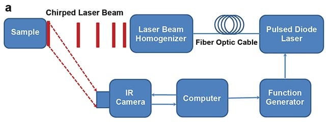
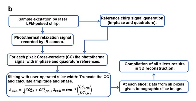
Figure 1. eTC-PCT (enhanced truncated-correlation photothermal coherence tomography) system
configuration (a). Reconstruction algorithm (b). LFM: linear frequency modulation. Courtesy of University of Toronto.
The cross-correlation evolves as the thermophotonic waves generated inside the sample reach the imaged surface conductively, radiatively, or in combination. These thermal transients carry information about the morphology and optical and thermal properties of the layers beneath the surface, with information from deeper layers taking a longer time to arrive conductively at the surface. The calculated cross-correlation is then truncated at consecutive time points using the time-evolving/gating filter, controlled by an operator-selected slice width, to provide depth-resolved information in both amplitude and phase-based contrast channels. Subsequently, for each time point, compilation of the data from all pixels leads to a depth-resolved 2D-slice image of the sample.
Finally, stacking and compilation of all 2D slices results in a 3D tomographic reconstruction of the thermophotonic image. This algorithm is summarized in Figure 1b. eTC-PCT axial resolution is determined by both the sample optical and thermal properties and the user-selected slice width, where a shorter slice width results in higher axial resolution but lower signal-to-noise ratio, and vice versa. The parameters of the system (e.g., laser pulse width and power) are optimized for biomedical applications and are maximum permissible exposure (MPE)5 compatible.
Dental thermophotonic imaging
Tooth decay (i.e., dental caries) is the most common oral disease in humans and certainly one of the costliest for health care systems. If detected at onset, caries can be treated noninvasively through remineralization. Yet radiographs, the primary dental imaging modality used today, fall short of this objective. X-ray imaging has low contrast and sensitivity to early caries, especially when beam direction is perpendicular to the imaged surface (for example, buccal/lingual surfaces in clinical scenarios), and also employs ionizing radiation, making it unsuitable for routine and frequent monitoring of patients due to potential health risks. These factors make radiographs unsuitable for preventive dentistry practices.
Dental eTC-PCT has shown high sensitivity to early caries, besides being nonionizing. Figure 2 shows an extracted tooth sample with a large carious lesion (seen as a hole) only visible from the distal surface. The opposite surface (mesial) was directly imaged and the lesion structure was reconstructed in 3D by compiling the 2D tomographic slice images provided by eTC-PCT based on thermophotonic data from increasingly deeper subsurface points6.
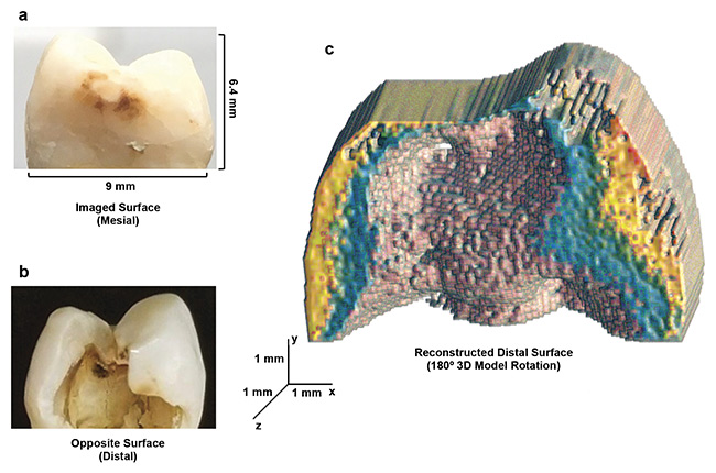
Figure 2. eTC-PCT 3D reconstruction of advanced dental decay. Mesial and distal surfaces, respectively, of a tooth with a large, cavity-like, carious lesion only visible from the distal surface (a, b). The 180° rotation of the 3D thermophotonic image taken from the mesial (outer) surface, showing the reconstructed distal face (c). The data clearly demonstrates the eTC-PCT structural modeling and boundary delineation capability. Courtesy of University of Toronto.
Lesion detection is achieved through combined higher absorption coefficient and thermal-wave confinement within the lesion boundaries compared to healthy enamel at the excitation wavelength. The combination leads to contrast amplification through higher amplitude and smaller phase lag for the thermal waves generated in the lesion region.

As this sample showcases, 3D dental thermophotonic imaging has the potential to be leveraged for dental clinic use — namely, the detection and imaging of early caries. An example is presented in Figure 3, showing the results for an extracted tooth with faint traces of caries on its mesial surface. The presence of early caries in the outer half of the tooth enamel was also confirmed via a sagittal micro-CT image — the gold standard for this information. While the x-ray revealed a hidden crack inside the tooth, it was not able to detect the incipient caries. eTC-PCT, however, successfully detected both the carious lesion and the hidden crack, and was able to provide a 3D tomographic signature of the extent of the lesion inside the tooth, located behind the mesial surface.
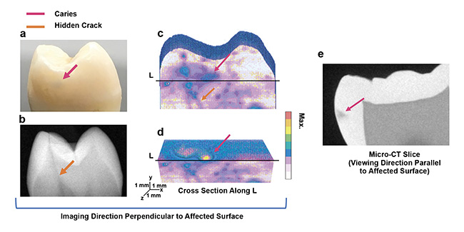
Figure 3. Application of eTC-PCT to early caries. Interrogated mesial surface of dental sample and its x-ray image. Color arrows point to initial caries (not visible in x-ray), enamel, and hidden crack (visible in x-ray) (a, b). eTC-PCT reconstructed 3D image of the mesial surface showing the caries and the crack (c). A transverse cross section of this reconstruction, cut along line L, as marked. Caries are seen extending inside the tooth over the cross section (d). Sagittal micro-CT slice image, showing the location and extent of the caries behind the mesial surface (e). Courtesy of University of Toronto.
Detection of early cancer
Early detection of cancerous tumors increases the chances of treatment and cure of patients. Biothermophotonic imaging has been applied to noninvasive 3D tumor imaging of animals. Cancerous cells were injected into the thigh of a mouse, and the evolution of tumor in the thigh was monitored noninvasively using eTC-PCT imaging performed before the injection of the cancer cells, and subsequently, three and nine days after the injection. Afterward, the mouse was euthanized and the leg skin was removed. The tumorous tissue was then collected and the tumor verified at Princess Margaret Cancer Centre in Toronto using histopathology analysis.
In Figure 4, the 3D image taken on day three is compared with the pre-injection image. The excised tumor sample geometry exhibited excellent correspondence with visible-light photographs after euthanasia. The shape of tumor structure in the eTC-PCT images was consistent with both the histology image and the visible photograph of the excised tumor7. Imaging of the whole mouse thigh before and after cancer cell injection was performed with high speed (less than 80 s), which is typical of this type of imaging.
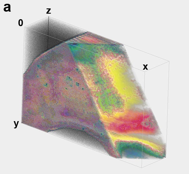
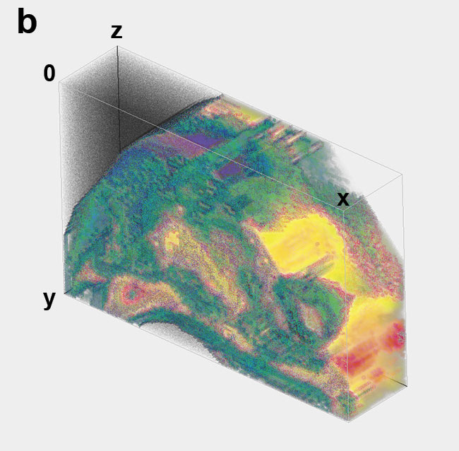
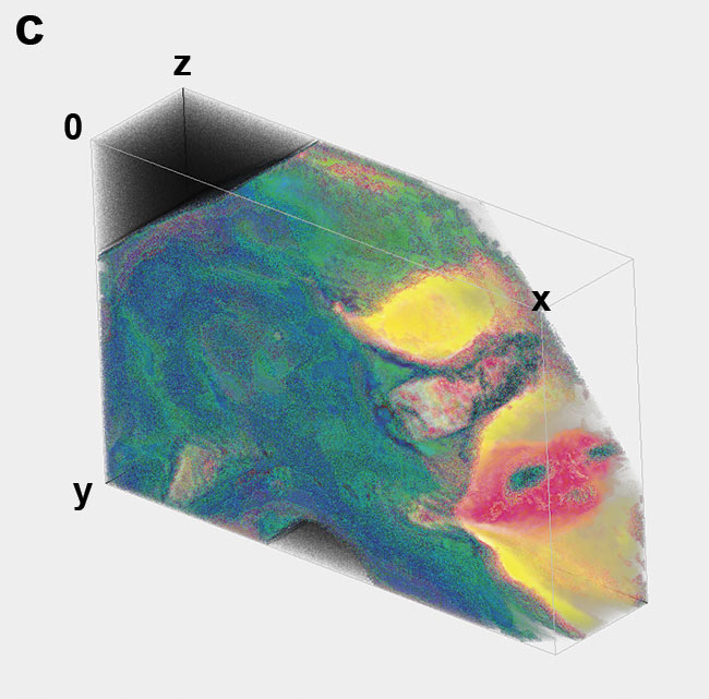
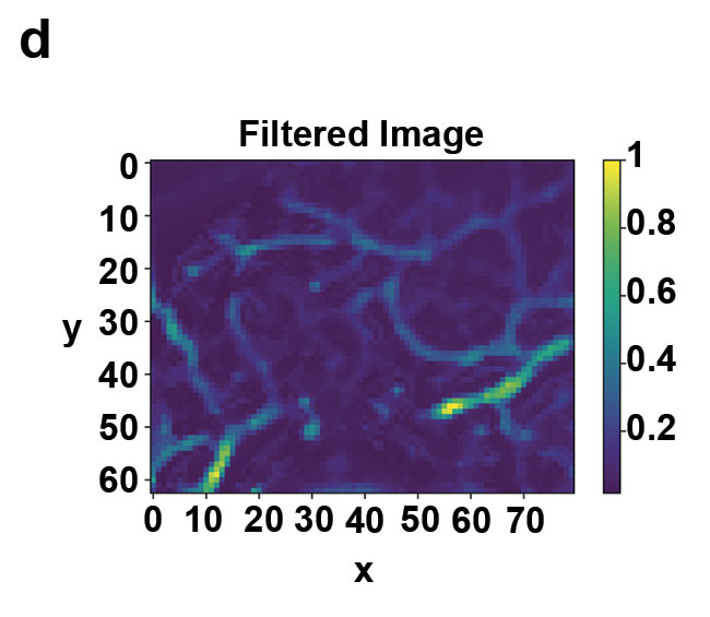
Figure 4. Tumor growth imaging in a live mouse thigh. 3D eTC-PCT amplitude image of the thigh with the right corner removed before tumor injection (a). Amplitude image of the thigh on day three after injection of the cancer cells in the tissue, revealing the penetration depth of the tumor (b). Amplitude image of the thigh nine days after injection of the cancerous cells (c) and 2D filtered image of the tumor on day nine, providing more details of blood vessels (d). On day three, tumor size is much smaller than on day nine. Image size: 1.35 × 1.08 cm; depth scale: ~2 mm. Courtesy of University of Toronto.
Future of biothermophotonics
Biothermophotonics is an emerging technology that requires further development to address real-life noninvasive diagnostics, starting with outer and exposed regions of animal and human tissues. It has excellent prospects for further development in minimally invasive endoscopy, enabling 360° imaging of plaques and lipids in atherosclerosis, for example. The current eTC-PCT imaging modality represents a first, yet crucial, step in harnessing photothermal phenomena to meet the demands for high-resolution 3D imaging of early-phase biomedical and dental lesions. It can be superposed — for example, with passive infrared thermography to provide co-registered molecularly specific biomedical imaging within an easier-to-analyze surroundings framework, superimposing images of body tissues — in ways that parallel the widely used photoacoustic and ultrasound co-registration.
As of this writing, eTC-PCT can provide a lateral resolution of 33 µm, and up to 3.8 to 4.0 mm of depth penetration in teeth and soft tissues. Further improvements in depth resolution are expected as more powerful optical sources such as pulsed lasers are used, with the implementation of a pulsed Nd:YAG laser generating pulsed chirps and an OPO (optical parametric oscillator) to develop multiwavelength TC-PCT. Detection of very early tumors points to potential for using the eTC-PCT method for cancer detection and treatment studies, and for preclinical/clinical cancer studies and animal drug testing. Portability and relatively inexpensive instrumentation is central to future widespread use in remote areas and off-hospital facilities.
Meet the authors
Pantea Tavakolian, Ph.D., is biothermophotonic imaging scientific manager at the Center for Advanced Diffusion-Wave and Photoacoustic Technologies. She received a doctorate in engineering and her research explores the development of new thermophotonic imaging systems with performance beyond current (photo)thermal imaging technologies; email: [email protected].
Sohrab Roointan graduated with a master’s degree in mechanical engineering from the University of Toronto, where he was a research assistant at the Center for Advanced Diffusion-Wave and Photoacoustic Technologies in the Department of Mechanical and Industrial Engineering. His master’s thesis focused on the application of novel photothermal imaging technologies to dental imaging; email: [email protected].
Konesh Sivagurunathan, Ph.D., is a research associate at the Center for Advanced Diffusion-Wave and Photoacoustic Technologies, in charge of software development for imaging data acquisition and reconstruction technologies at the center; email: [email protected].
Andreas Mandelis, Ph.D., is professor and director of the Center for Advanced Diffusion-Wave and Photoacoustic Technologies in the Department of Mechanical and Industrial Engineering, and cross-appointed to the Institute of Biomedical Engineering, at the University of Toronto; email: [email protected].
Acknowledgments
The authors are grateful to CIHR and the NSERC for a CHRP grant to A. Mandelis; to the Canada Research Chairs Program; to the CFI-JELF Program and to the NSERC Collaborative Research and Training Experience (CREATE) program.
References
1. A. Mandelis et al. (2001). Structure and the reflectionless/refractionless nature of parabolic diffusion wave fields. Phys Rev Lett, Vol. 87, Issue 2, p. 020801.
2. S. Kaiplavil et al. (2014). Truncated-
correlation photothermal coherence tomography for deep subsurface analysis. Nat Photonics, Vol. 8, pp. 635-642.
3. P. Tavakolian et al. (2017). Enhanced truncated-correlation photothermal coherence tomography with application to deep subsurface defect imaging and 3-dimensional reconstructions. J Appl Phys,
Vol. 122, Issue 2, p. 023103.
4. P. Tavakolian et al. (Aug. 13, 2020). Non-invasive in-vivo 3-D imaging of small animals using spatially filtered enhanced truncated-correlation photothermal coherence tomography. Nat Sci Rep, Vol. 10,
p. 13743, www.doi.org/10.1038/s41598-020-70815-3.
5. Laser Institute of America (2007). American National Standard for Safe use of Lasers. (No. 12ANSI Z136). 1-2007.
6. S. Roointan et al. (2019). 3D dental subsurface imaging using enhanced truncated-
correlation photothermal coherence tomography. Nat Sci Rep, Vol. 9, p. 16788.
7. P. Tavakolian et al. (2019). Truncated-
correlation photothermal coherence tomography derivative imaging modality for small animal in vivo early tumor detection. Opt Lett, Vol. 44, pp. 675-678.